More tinkering happened today. I also had time to make an organizer for my prototyping setup. More details after the break!
There are a bunch of ways that you can do measure liquid levels. I found a great post on Digikey about the different methods used.
After I was able to get water level measurement in place, at least in the Arduino firmware, I wanted to do a few full “discharges” to ensure that the ADC curve would be easy to adapt to for limiting. (i.e. making hard limits for the fullness gauge on the homepage).
Note: I did attempt a capitative measurement (personal preference) using a GPIO interrupt and a timer but I wasn’t getting consistent results. I’m not sure if it’s because of the extra cruft in the Arduino code or the GPIO interrupt is just that flaky.
I’ve included a rough idea of how it went down below:
Ingredients
Here’s a list of ingredients I used to make it happen:
- 6' piece of Super Conductive copper rod (McMaster [8965K41](http://www.mcmaster.com/# catalog/120/3763/=r6yce4)
- 1' piece of insulated dual conductor wire (recycled off of a power supply)
- 1 small piece of breadboard jumper wire
- A few other pieces of jumper wire
- 1 1k resistor
- 1 full-stack proto board
Tools
- Dremel with metal grinding disk
- FX-888D Hakko Soldering Station with a thick tip
- 19 AWG Thick Solder (on a spool)
Process
Here’s the (very) abbreviated process I went through to get things working:
-
Cut the copper rod.
I cut two exact duplicate pieces of rod. I made sure that they were almost as deep as the water container.
Note: make sure that they are still shorter than your intake!
-
Solder the copper rod.
I placed the freshly cut rod in a vice, cranked up my soldering iron (850°F), and added solder to one end on each rod. Remember, copper conducts heat quite well so your soldering iron will have to be quite hot to compensate.
-
Solder the wires to the copper rod.
Place some solder on the wires before attaching to the rod (makes things much much easier). Then go ahead and affix the wire to the rod.
-
Strip an solder the opposite ends of wire and add solder.
Now, take the opposite end of the wire (the unsoldered end), strip about a centimeter off each tip and add add solder.
-
Solder solid core breadboard wire.
In order to get this setup attached to a breadboard, I affixed some breadboard wire to each wire lead.
-
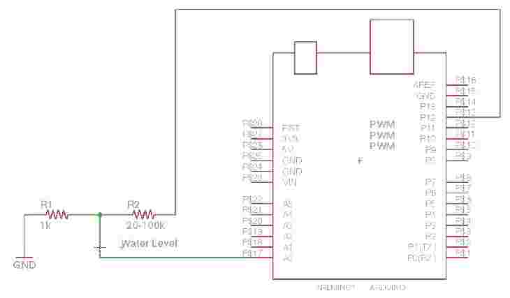
Assemble the remaining schematic.
Here’s the schematic for the measurement setup:
Here’s the finished circuit:
Note: I measured from about 20k ohm to about 100k ohm for the resistance range between the copper rod in the water. If you use a different container, wire, or rod your mileage may vary.
-
Insert rod into the cap.
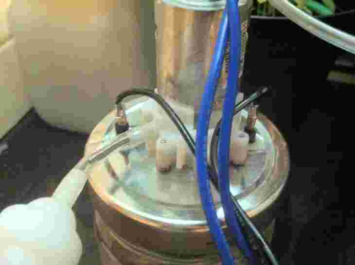
I used some dry wall anchors and some electrical tape to hold the rod in place. (and keep it insulated as well).


The measurement
I made a few measurements at different intervals to get an idea of the relationship of resistance versus water level for sanity sake. The first involved turning on the motor at 1 second intervals until empty and the second measurement used 2.5 second intervals until empty.
As you can see from the plot above, the relationship is nice and linear! That means programing limits is going to be a piece of cake. I will still need to account for some tolerance and will probably add some software hysteresis as well to account for jitter.
I used a python script and pyserial to execute the following instructions.
Note: I had a horrendous time getting pyserial to act nicely with the Arduino. I don’t quite remember having these issues previously. The biggest problem was when I wrote data to the serial port during the early stages of the program I would receive no data back when I expected it. I ended up fixing this cringe by adding a few second delay before continuing. Nevertheless it must be some FTDI driver issue or something related to OSX 10.9. I digress, back to the code.
while ADC_VALUE > 0:
    Get the current ADC_VALUE
    Save the ADC_VALUE
    Turn on the motor
    Wait X seconds
    Turn off the motor
    Repeat
Prototype Board Setup
As mentioned before, I threw together a All-in-One Full-Stack prototype board. I was tired of dealing with loose wires especially if I had to remove or re-add something to the circuit. Here are some pictures of the setup below:


I’m curious as to what you guys think. Useful?
What’s next
I’ll be working on integrating the water measurement into the UI in the next few days. There’s lots to do and not enough hours to do them in!
Stay tuned for more posts!
Cheers,
Jared
Last Modified: 2020.3.7