No matter how much you research and design a circuit board, sometimes things still go wrong. And nine times out of ten, it’s due to human error.
In part two of Dimming AC lights With A Micro-controller, I go into assembling my circuit boards and then testing them. I create a fireworks show on my bench but managed not to burn the house down.
If you’re curious how I got here, go check out part one.
Also, before we start, playing with mains circuitry is dangerous. The purpose of this post is for educational purposes only. Let the professionals handle the scary stuff. 😉
Assembly: Check and Double check.
It’s not uncommon to put parts in the wrong place or reverse polarity. Usually in lower voltage circuits, this doesn’t matter. But in higher voltage mains applications, things can go wrong, fast.
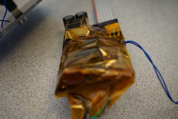
I took some precautions before testing. This included using a surge protector strip with a separate on/off switch. That way I could kill power to the circuit if something went wrong.
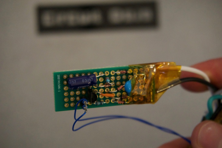
For safety sake, I also wrapped the AC board in Kapton. That way I was isolated from the high voltage bits. I also taped the wires in place so they wouldn’t pull the PCB onto the floor.
The best way to connect the mains to the circuit board is to use an old power supply cable. I cut the end off and then used wire strippers to get to the wires on the inside.
Once everything was wrapped, I plugged it in and fired it up. And boy, did it fire up.
I heard a pop and something fly around just beyond the Kapton.
Shit.
The damage was minimal, but I didn’t have the parts to fix it.
So a quick order for some more parts was in order. There was still the question of what went wrong.
So after some trial and error and another similar explosion, I had to trace the path from the AC input all the way to the input of the switching regulator.
And bingo.
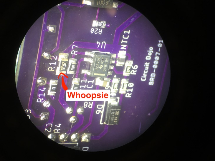
Somehow along the way the Base-Collector-Emitter of the STX13005 BJT transistor I was using was oriented in an Emitter—Base-Collector format. i.e. I had created a diode out of something that should have been a switch.
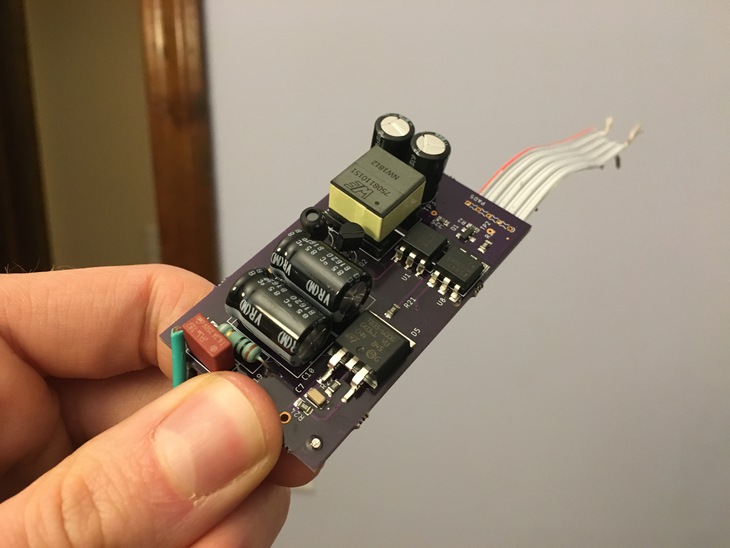
Fortunately, if I bent the leads just right, I could get it in the correct format. If you look at the picture below you can see the TO package slightly twisted.
Straight forward solution that required no board modifications. That’s the type of rework I like. 😎👍
The Testing Continues..
So, even though I was almost certain about the solution to this problem I was even more paranoid about burning the house down. So, I re-wrapped everything after my fixes, connected it to a power strip and connected the multimeter to the 5V output.
Hesitantly, I moved my finger to the power strip’s button.
Three… two.. one…
..
To my delight, the circuit powered up and I was seeing a sweet 5V as expected on the output.
Awesome.
My next step was to see if I could get the zero-cross circuitry working. I set everything back up near my oscilloscope to do some measurements. After hooking everything up though, I got nothing. Something else was wrong!
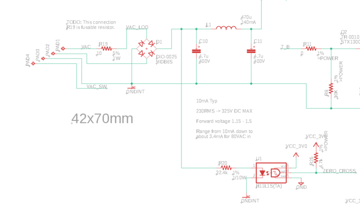
After a quick review of the circuit (again) I realized that I would need a smaller current limiting resistor in order to get the optocoupler to turn on. (See R20 below)
The bigger problem?
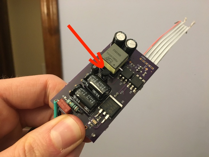
The surface mount resistor I had was a 1/10W resistor. The power going through that same resistor would be > 1/4W. Yikes.
The circuit would not do. I tried to finagle a few resistors in series and in parallel, it wasn’t an elegant solution. This resistor blob, as I affectionately will call it, did not pan out. So much so that the heat from the blob caused the solder to melt.
I was not ready to play these reindeer games so the search was on for a better circuit.
Zero Cross Circuit Search
So I scoured the internet a bit more to look for something suitable. I opened one site using Archive.org and low and behold a circuit that was perfectly suited for the job. The original circuit is included here. 100% attribution goes to the author.
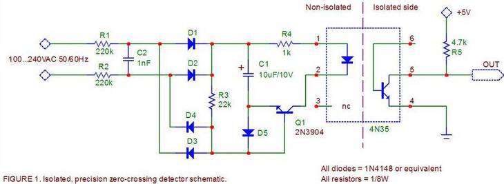
The first half of the circuit (R1/R2) reduces the voltage seen by a separate full wave rectifier. There’s also a handy cap (C2) to allow noise to bypass the rectifier all together.
The second part charges up a capacitor which, at the zero crossing point, supplies the LED current for a short amount of time. As the AC voltage fluctuates, the process occurs over and over.
Now, the problem was how to implement this circuit.
Spin another board?
Prototype on a breadboard?
I ended up choosing to prototype it on a breadboard. This whole process was the inspiration for my previous post debating the subject.
The final product looked like this:
The most important part was wiring the zero-cross signals to the optocoupler on the other board. I used a separate power supply cable that I modified similarly to the main circuit board.
Developing the Firmware
AC dimming is not disimilar to the concept of PWM. The phase is cut depending on the intended brightness. So, the brighter, the fuller wave you get. The more dark, the less of a wave you get.
In my case, I was modifying the AC wave by reducing the “on-time.” I simply configured the pin connected to the output of the H11L1S. That interrupt triggers a timer start. Then, when the timeout occurs, the TRIAC is finally switched on. The process continues after each zero-crossing event.
(By the way, I’m using the Nordic SDK for this particular project. For some fo you these calls may look familiar. Especially the nrf_gpio_pin_clear and app_timer_start calls)
static void zc_pin_evt_handler( nrfx_gpiote_pin_t pin, nrf_gpiote_polarity_t action ) {

  if( pin == m_config.zero_crossing_pin ) {

    // Don't do anything if it's a static state.
    if( m_state.brightness ==0 || m_state.brightness == MAX_BRIGHTNESS) {
      return;
    }

    // Turn off Triac pin
    nrf_gpio_pin_clear(m_config.output_control_pin);

    //Start timer at known interval
    app_timer_start(m_pulse_start_timer_id, APP_TIMER_TICKS_US(m_state.on_time_us) ,NULL);
  }

}
One important thing to see here is that I use a steady state for the off and on states. There’s no reason for this event handler to do anything if that’s the case.
Here’s the timeout handler.
static void timeout_handler( void * p_context ) {
  // Turn on the Triac
  nrf_gpio_pin_set(m_config.output_control_pin);
}
Talk about simple.
The calculation to determine the on time is fairly simple as well:
m_state.on_time_us = DEFAULT_MAX_PERIOD_US - (DEFAULT_MAX_PERIOD_US / MAX_BRIGHTNESS * m_state.brightness);
Where the max period in microseconds is from 0 to 180° of phase (around 8.33ms). Where max brightness, in this case is 0xFF (255).
After some finagling, I managed to get a video of the whole thing in progress:
Here’s also a few pictures of the setup and how I connected the dimming circuit board to the actual light I was testing with.
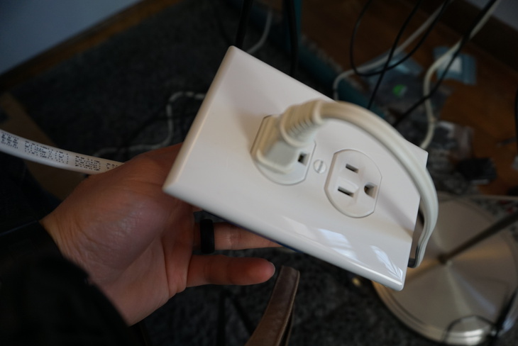
I used a standard electrical box and outlet to connect to my PCBs. This way I could test ‘as if’ the circuit was placed inside the wall. I even wired it similarly. (See below)
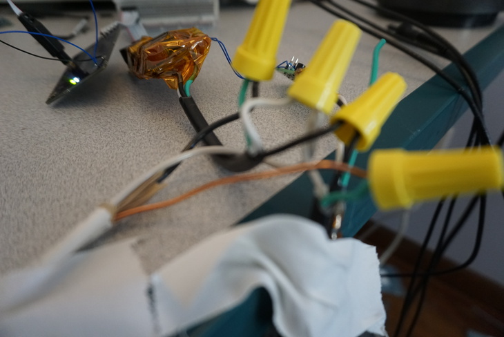
As you can see, wire nuts were my connector of choice. I had to break down the circuit a few times to make modifications. So the easier to take everything apart, the better.
Next post
I’m thrilled with the results but there’s more to do. I found that there was a significant amount of noise on power rail supplying my touch chip. This voltage needs to be super clean (max ±25mV) in order for the AT42QT2120 to register the touch slider properly. More on this in the next post.
Next time I redesign the circuit boards. Plus I play with the Bluetooth Mesh functionality which makes this experiment more interesting. So stay tuned!
Also, some exciting news here, I just spent a few weeks in Taiwan and met with some great circuit board fabs and an impressive assembly house. If you’re looking to fab and/or assemble circuit boards subscribe to my email below for further details.
What do you think about this series thus far? Let me know in the comments box below.
Last Modified: 2020.3.7