In this post I’m going to talk about how to control AC circuits from a DC powered device. You can go crazy when it comes to this stuff. So my main goal was to keep it simple.
- Be mesh enabled for future improvements
- Have the ability to dim the connected lights
- Have a way to control the dimming functionality
The requirements above necessitate a few circuits that need to be mushed together. At the very least, a power supply, and a way to switch the high voltage power and a way to control it. Anything outside low voltage DC is uncharted territory for me. Therefore, I’ve leveraged lots of internet resources to get up to speed. I’ll include links that I found useful as we go along.
First though, I need to be official. 🤓
Warning: this post is for educational purposes. Working with mains voltages and raw rectified DC voltage is dangerous and could cause harm or death. I assume no liability if you chose to make and energize these circuits yourself.
Now that that’s out of the way, let’s get to it!
Getting your DC
The first thing I thought about was how can I power this thing. I wanted to keep the design as flexible as possible. So, accepting different input voltages seemed to make sense.
So, let’s say the input voltage range is 85 to 230 VAC. How do you get a nice 5 VDC out?
Let me show you what most modern power supplies do:
- You plug in your charger/power supply into AC mains
- You rectify those mains to get a rough DC signal
- Filter it
- Pass it through a transformer driven by a integrated circuit and MOSFET or BJT
- Rectify and filter the isolated output voltage
- Enjoy your DC voltage 😋
The most complex portion of the setup is controlling it all. From my research, one of the typical integrated circuits used is a primary side constant voltage controller.
Say what huh now?
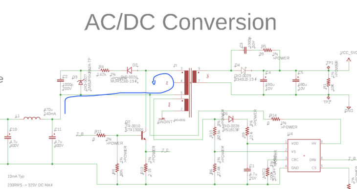
A primary side constant voltage controller uses raw rectified DC voltage and steps it down though a transformer. Most of the controllers out there are used in a flyback topology. The concept of a flyback is similar to any switching regulator you may see for DC applications. (Think buck regulator… but different. See below.)
- Current is pushed through the primary coil.
-
A field is generated and potential energy gets stored in the coil.
-
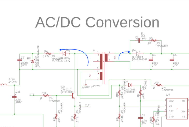
The switch to ground is turned off for some time. Which allows the energy in the magnetic field to dissipate. This is the point where current will flow into your low voltage circuit. Note on the left side that any energy on the primary side will be dissipated by the clamp circuit.
- The path to ground is activated again and the process repeats.
This design uses an auxiliary winding as feedback. The feedback is used to keep the output in regulation. That way you have a clean voltage. Without the feedback, the controller wouldn’t be able to regulate for sudden changes in current. Therefore, no 5V for you! 👨🏻🍳
If you want to learn more about the inner workings of this circuitry you should look at the design I based this off of. TI also has a great white paper describing how the flyback concept works.
One of my favorite examples of this type of circuit is what you probably use every day, the wall charger. In particular, it’s the core of what is affectionally known (to me and a few colleagues from Apple) as “The Marshmallow”.

This USB charger translates a wide range of AC voltages to 5V DC. All doing it with in a tiny footprint. I recommend reading through the teardown on Ken Shirriff’s blog. He had some great insights about the innovative design of the Apple Marshmallow. After reading it you’ll have a healthy appreciation for the technology that goes into such a small package!
In terms of low load efficiency, a primary side controller doesn’t do well. The reference design I mentioned before is roughly 70% efficient at 100mA. The circuit that I intend to use will only need 5-10mA. My best guess is that the efficiency will be worse.
On the flip side, If you’re in the market to find a switching AC/DC circuit you’re in luck.
There’s a lot of choices.
To help you in your journey, here’s TI’s page of reference designs. You can also use their Webbench tool to simulate and generate circuit recommendations. The only drawback is that the tool always recommends a custom coil. As far as I know, there’s no easy way to get one-off custom coils. If you’re a coil assembly house, i’d love to chat to learn more about your business!
Finally, before going on to the fun stuff, safety should be on the top of your mind when designing anything with higher voltages. There’s some documentation on safety from TI. I highly recommend it especially if you find yourself designing your own board.
Controlling The Load
I’m a big fan of relays. They were the first electronic device I came to understand as a young enthusiast. They unfortunately can’t be used to dim a connected load.
So what’s an engineer to do?
Push into the challenge. 😉
My second choice was to use a TRIAC (triode for alternating current). Upon first glance they were a bit of a mystery to me. The symbol looks like two diodes connected in parallel with opposite polarities. The concept though is similar to that of a BJT. You flow current through the “gate” which allows current to flow in either direction.
Awesome. TRIAC. Done, right?
Well, how does one safely switch a TRIAC? Plus, how does one switch it with as much protection and isolation between DC and AC?
The main way this is accomplished is with an opto-isolated TRIAC. See the bottom circuit in the below capture:
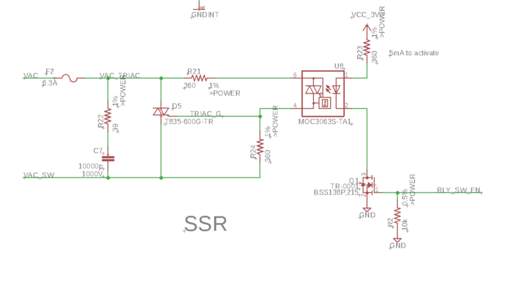
The opto-isolated TRIAC circuit I used was right out of ON Semi’s data sheet. The resistors and snubber circuit are used to prevent spurious on or off transitions. This is due to the resonance effect of the load current. Luckily, there are also “Snubberless” parts from ST which require less external components.
So, in order to turn on the power TRIAC, current needs to flow through the internal LED of U8. Then, the opto-isolated TRIAC allows current to flow into the gate of the power TRIAC. This part does have zero-crossing detection so it will only switch on when the phase has hit 0V. More on zero-crossing in the next section!
A final note: safety is important. I’ve placed a lower current rated fuse leading to the power TRIAC. I believe the power TRIAC I chose is rated 8A.
Zero Crossing and Phase Cut
Update 1/23/2019: I did find another suitable Zero Crossing circuit here. I originally passed on it because it didn’t load. Thanks to the internet archive, I was able to pull it up and save it into my Pocket for later. I’ll update this article again when I have a new schematic.
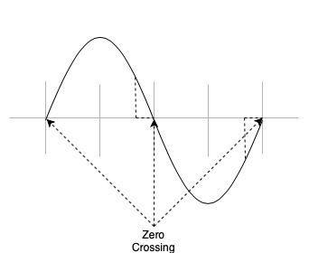
As I alluded, the opto-TRIAC uses zero-cross detection. It is used to prevent inrush current which would damage the load. I found a great explanation of why zero crossing detection is important on stack exchange. The author goes on to pose the question: “Haven’t you noticed that most incandescent light bulbs burn out when you flip them on?” That’s because the switch is getting turned on when the phase is at its peak voltage. The instantaneous current is what “blows up” light bulbs.
Mind blown 🤯
The same concept can be used for switching other devices. For instance, switching a motor. You can wait for the phase to hit zero, then switch on your TRIAC. That way, as the phase progresses, there is less stress or shock on the device being powered.
Makes sense, no?
So, How does this apply to dimming lights?
On the micro-controller side, zero cross detection is still useful to know when to switch on but also when to switch off.
Let me explain.
TRIACs have been used since the 60’s. They’ve been put in all types of dimming circuits. Some of which I bet you use every day.
That circular dimmer in the dining room? TRIAC.
Sliding dimmer in the living room? TRIAC.
These devices work by switching off the TRIAC in proportion to the slider or knob position. I go into the comparison between a regular AC and then AC signal post TRIAC dimmer in the next section.
Phase Cut Using a Microcontroller
Now that we know the importance of zero cross. Plus, we know that we can control a TRIAC from a micro-controller. The next step is to get that zero cross feedback into the micro-controller so it can be both switched on and off at the right times.
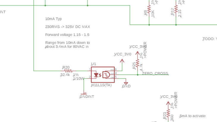
The best way that I have found to determine zero crossing for the Microcontroller is by using a H11L1s. It’s a Schmitt Trigger photo-coupler. The bigger question here is, how?
Well, once you have rectified AC voltage you get a repeating half-wave that looks something like this.
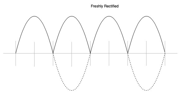
The black line is the input for the H11L1s. The dotted is what the un-rectified AC signal looks like. As the rectified signal reaches zero, the H11L1S turns off and the output signal goes “high”. As the phase changes it increases again and the output turns back on driving it to zero. We now know where our zero-cross is!
The H11L1S in particular has a forward voltage of 1.15 to 1.5V. If you remember our input voltage requirements at the beginning, I wanted this circuit to work with 85 to 230VAC. That means the peak “DC” voltage seen at the device will be 230 * sqrt(2) (as 230 is the RMS voltage) This leads us to a max of 325V. For the 85VAC condition we’re talking about 120VDC max
Therefore, we have to set a current limiting resistor so that the optocoupler works in all conditions. According to the data sheet it turns on at 1.5mA forward current.
Calculating out with a forward voltage of 1.5V, we require a 32.4kΩ resistor. Our current is limited from 10mA down to about 3.5mA. Peerrrfecto.
The circuit i’m using is included below:
It’s important to know when the zero crossing happens for the micro-controller. If the micro-controller knows, it can control the phase and “cut” it to lower the average power seen at the output.
The way I plan on cutting phase is in the reverse to most TRIAC circuits . See below what the waveform would look like.
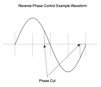
I’m using the zero crossing to turn on, then wait depending on the duty cycle, and finally switching off the circuit before the next zero crossing. This way, there’s a less transient response on startup. The dotted lines is where the output voltage is “cut” reducing the output power. More on the difference between forward and reverse here.
List of resources
Well, it’s almost time to say goodbye. If you’re interesting in learning more, here’s a list of all the resource I found during my search. These were the most useful and were the basis for this article.
A huge shoutout to Lewis Loflin @ www.bristolwatch.com. His resources on the subject are superb. I found the most useful ones below:
Here are some other unaffiliated resources:
- TRIAC vs PWM?
- Application Note from ST
- Ambient Light Monitor: Zero-Cross Detection
- Triac and Home Appliances
- Dimming Control White Paper
- Great Post on AllAboutCircuits
- Web Archive of a great article on zero-crossing
- Zero Crossing Detectors and Comparators
Conclusion
My boards are out to fabrication as I write this. Stencils are ordered. Parts are ordered. (Some are already in-hand. Arrow Electronics has free 1 day shipping right now, who can complain about that?!) I’m excited to both test the circuit and see how it keeps up with the relatively low current of my logic circuitry.
Update: Part 2 in this series is out!
Last Modified: 2020.3.7