In the beginning, there was nothing. Then, you figure it out and go from there.
- Someone Wise
Every project has it’s beginnings. Mine began with a simple hypothesis:
“Could I, using the Particle Photon, to monitor a wood-stove for a winter season running on two AA lithium batteries.“
So, there were two things to think about during this process
- Constraints of the batteries
- Functionality of the design
In order to get the best battery life, the system has to be in a very low power draw state most of the time. The best way to do this, especially if you’re, for example, reading temperature sensors on a consistent duration, is to power everything off except for a Real Time Clock (RTC) for time keeping and to power things on when it’s time to make a measurement.
The typical power draw of the RTC that I had development board was about 450nA (that’s NANO amps people!) at room temp. By the way here’s the specific part I’m using: NXP PCF85063ATL
Whereas the DEEP_SLEEP mode draws about 10x that at approximately 100uA. (When I actually prototyped everything, I was getting much more which could have been due to a slew of different factors..)
Either way, I wanted for this device to last a season of wood burning. Worst case 24/7 for folks who are in the northern boonies.
So, what’s the process to put everything together?
Well, first you need to think in blocks.
You take the circuits that you may need to integrate, for example a display, LEDs, power supply, the temperature and humidity sensors, and the thermocouple amplifier and think of them as discrete blocks. Then you figure out if you can create those blocks in circuit form or purchase them off the self. The later is usually in the form of development boards, where often lots of the heavy lifting has been done for you.
I’ll get into the nitty gritty details later but first we need to think about the relationships between said blocks.
You are the architect.
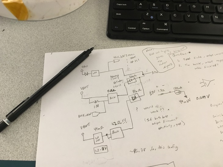
There’s a bajillion ways to get our ideas down into a formal architecture. Sometimes it’s drawing out the blocks on a piece of paper with some pencil. Thinking about how it could work, erasing, fixing, and trying again.
For designs that don’t require as much iteration, I use draw.io. It’s basically an in browser Omnigraffle on steroids and perfect for organizing blocks together to show the relationships.
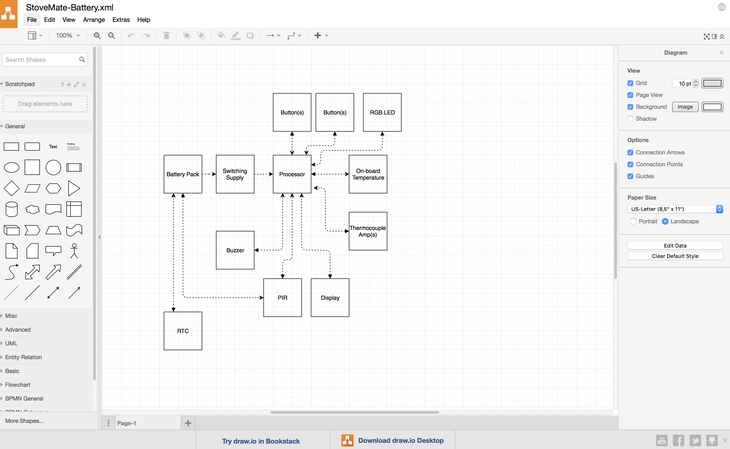
You can export to XML, PDF, image (or basically any format that you could think of) and re-import should you want to make changes later.
The above diagram was the “finished” version to show what the system may look like before testing any hypothesis. Not only is it great for visualizing but it’s also handy for the next step: connecting everything together!
Also, here’s the raw XML source so you can download and open the file in draw.io.
Get the puzzle pieces together
Alright, nows the time to acquire those blocks that we’ve now cleverly organized using draw.io or pen and paper.
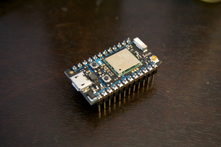
Here are the development boards that I used get everything up and running.
Note: one of the main reasons for so many Digikey links is their mindbendingly fast warehouse. I can consistently get things in two days if I order before 8p CT. I don’t even bother half the time ordering directly from Sparkfun or Adafruit because they’re just too darn slow.
Luckily I already had most of the important pieces on hand at home. So it was a trip to Digikey for the thermocouple development board, a Photon board and 7 segment display + driver.
Two short days later, wiring them together took less than an hour and I was compiling some Hello World code within that same timeframe. It’s probably the fastest I’ve gotten functionality out of so many devices at the same time.

 Here’s another one thanks to Kevin A’s suggestion!
One of the reasons I was so speedy was because of the prototyping techniques used. As you can see above, I utilized both wire-wrap and a solder-less breadboard to make all the connections. I love wire-wrap enough that I wrote up a guide on it. Needless to say, you should get familiar with both if you haven’t already!
Now, some of you probably already clicked the links to the development boards above and nearly keeled over in your chair. They are a bit costly. For instance, the one that I bought for the thermocouple set me back about $75. But, was it worth it?
Yup, because if I spent the time on designing a board, spinning it, waiting for it to arrive, getting the parts, assembling it, and potentially finding issues, I would have been out a whoooole lot more money than that $75. Plus it already came with a thermocouple. 👌
Develop the code
Now that the “hard” part is done.. (get it) lets get to next step in our journey, ~the software.~
Between the Particle Reference documentation and the various data sheets for the parts I was using I was able to assemble the various bits and pieces to get every block minimally functional.
Let me save you some time and let you know what the default I2C addresses for each of the devices are because honestly we all know that’s half the battle right there.
#define RTC_ADDRESS 0x51
#define SI7021_ADDRESS 0x40
#define MCP9600_ADDRESS 0x60
#define DISPLAY_ADDRESS 0x70
After figuring out what the address was for the Si7021 (humidity + ambient temp), only two commands have to be issued in order to get both ambient temperature and relative humidity readings.
Here’s the exact code I was using
uint16_t get_onboard_temp() {
  // Si7021 Temperature
  Wire.beginTransmission(SI7021_ADDRESS);
  Wire.write(SI7021_TEMP_READ_CMD); // sends one byte
  Wire.endTransmission();           // stop transaction
  Wire.requestFrom(SI7021_ADDRESS, 2);

  // Serial1.print("temp:");

  uint16_t temp_code = (Wire.read() & 0x00ff) << 8 | (Wire.read() & 0x00ff);
  uint16_t temp = ((175.72 * temp_code) / 0xffff - 46.85) * 100;
  // Serial1.printf("%dC", temp); // print the temperature

  return temp;
}

uint16_t get_onboard_humidity() {
  // Si7021 Humidity
  Wire.beginTransmission(SI7021_ADDRESS);
  Wire.write(SI7021_HUMIDITY_READ_CMD); // sends one byte
  Wire.endTransmission();               // stop transaction
  Wire.requestFrom(SI7021_ADDRESS, 2);

  // Serial1.print("\nhumidity:");

  uint16_t rh_code = (Wire.read() & 0x00ff) << 8 | (Wire.read() & 0x00ff);
  uint16_t rh = ((125 * rh_code) / 0xffff - 6) * 100;
  // Serial1.printf("%d%%", rh); // print the humidity

  return rh;
}
What’s handy for each of them is that the chip uses clock stretching to hold the processor in place until the measurements are ready. That way there’s no polling or interrupts to worry about. The downside is that it’s blocking (i.e. the Particle technically can’t run any of your code while it waits) but it doesn’t matter in such simple project such as this!
The thermocouple IC was similarly organized. It required a read first to make sure the data was available and then another read of the compensated “hot” register.
float get_thermocouple_temp() {

  // MCP9600 Temperature
  Wire.beginTransmission(MCP9600_ADDRESS);
  Wire.write(MCP9600_STATUS_REGISTER_CMD); // sends one byte
  Wire.endTransmission();                  // stop transaction
  Wire.requestFrom(MCP9600_ADDRESS, 1);

  uint8_t status = Wire.read();

  // Check to make sure the sample is ready
  if (status & MCP9600_UPDATE_AVAIL_BITMAP) {
    // Serial1.println("Sample is ready");
  } else {
    Serial1.println("Error: Sample is NOT ready");
  }

  // MCP9600 Temperature
  Wire.beginTransmission(MCP9600_ADDRESS);
  Wire.write(MCP9600_TEMP_HOT_CMD); // sends one byte
  Wire.endTransmission();           // stop transaction
  Wire.requestFrom(MCP9600_ADDRESS, 2);

  // Serial1.print("\nt-temp:");

  uint8_t upper = Wire.read();
  uint8_t lower = Wire.read();
  float temp = 0;

  // Depending on if its positive or negative
  if ((upper & 0x80) == 0x80) {
    temp = ((upper * 16 + lower / 16.0) - 4096);
  } else {
    temp = (upper * 16 + lower / 16.0);
  }

  // Serial1.printf("%f\n", temp);

  return temp;
}
Writing the Particle firmware was taking me back to 2007 when I first started fiddling with Arduinos. The obvious advantage here is the whole Wifi functionality plus the integrated Over The Air update capability and web backend functionality.
I digress, once things seemed to be minimally useful, I set my sights on the hypothesis I had yet to prove or disprove.
By the way, I did upload the code thus far to Github here. For those who are interested I also made a separate branch, called powertest for the power measurements described below.
Test the hypothesis
You would think this is simple, right?
The goal here was to determine through some measurements and through calculation whether or not my device would make it a full season of burning.
One thing anyone should ever do before creating a battery life constrained project is to take a look at the data sheet. That’s usually the first litmus test of performance.
What we’re most interested in is the WIFI+Processor on current.
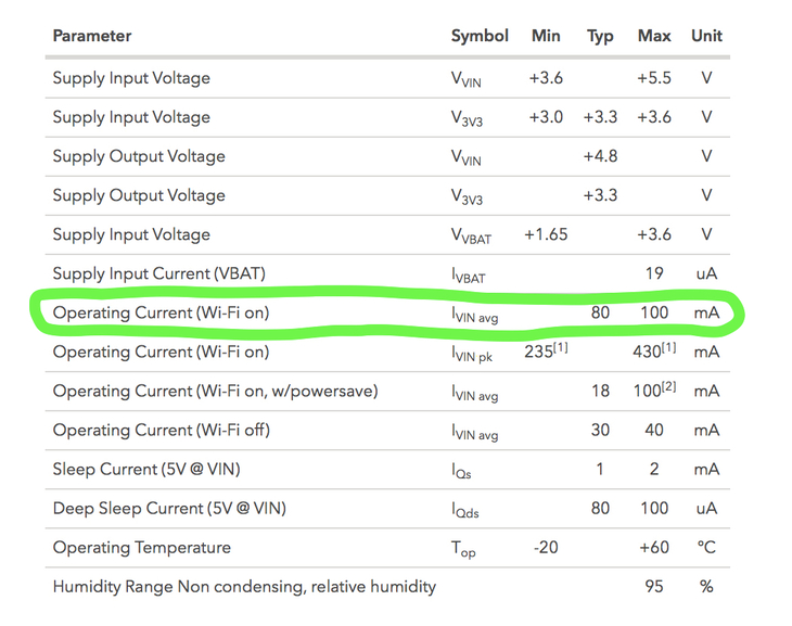
If you were to run this device 24/7 without any power saving measures you’d need 518.4Ah battery to last a whole season. So that idea is definitely out of the picture.
There’s also the Peak current to be worried about but typically this is instantaneous and only when transmitting. This is important for certain battery chemistries as it causes large voltage drops which may cause brownouts. (i.e. the power supply dips and causes the processor to restart)
Datasheets are great but they don’t always tell the full story. For instance, the Wi-Fi on, w/ power save is not exposed as an option in the Particle firmware. This could be a very useful mode for some but you wouldn’t know that you couldn’t use it until you tried!
So, I tweaked the firmware until I got it as optimized as possible.
- Power on
- Get measurements
- Connect to wifi and backend
- Push measurements
- Receive ACK
- Power off
Measuring how long this would take would be the deal maker or deal breaker. I used the transitions on the I2C as the start of them measurements and measured the output of my handy dandy uCurrent to see when it finally dropped off once done transmitting.

I saw results ranging from about 4 seconds all the way past 10 seconds. In most cases, if I waited about 30 seconds between updates, it would take about 7-8 seconds to update to the cloud. 8 seconds in the embedded world is a loooooong time.
I popped everything into the quick and dirty power model I made but kept running up against roadblocks. The frequency of measurements was important but I thought maybe when the burn is going good I could change the interval from 30 seconds to 5 minutes. That saved some power but even with that I could get maybe 64 days of continuous use and updates.
So, the hypothesis thus far is not looking good. At this point my investigations are on going but the idea of potentially updating 5-10 minutes of data at a time may save the prospect of running off of 2 lithium batteries. So stay tuned on that front. 😎
What if I really want to build my own?
Before I close up this post, some of you may think: “Why use a platform like Particle, they have my data, I have no control.” And to you I say: ”I agree” but what’s the difference between shipped products on a platform you can’t control and a non-shipped product with a half working platform that you do control? Likely the survival of your project and even company.
If you do find yourself wanting to roll your own solution. There are a few wifi module makers out there that have some decent product. See below:
Zentri (Silicon Labs) AMW007 - This particular module is relatively easy to use and can be controlled with a simplified command structure. They aren’t quite AT commands but close enough. There were some bugs, especially around sending encrypted data, but I believe they’ve been fixed since I last used this module
Espressif - everyone is clamoring about these super cheap pre-certified modules. I think they’re great but beware that some modules (at least the ESP-WROOM-02) are not so friendly for battery powered devices for some of the reasons I stated before about high currents and brownouts.
Wifi is, of course, one way to get the data out but theres other technologies like Thread and Bluetooth mesh which are maturing which really show some promise. I even ordered some of Particle’s mesh ready dev-boards which utilize Thread. More on that soon.
Looking for a Particle power temperature sensor on steroids? Check out my latest one here.
Last Modified: 2020.3.7