Prototyping can open your eyes to the possibilities or the constraints that you now have to create a product. For instance if you 3D print a prototype and find that it’s darn near impossible to hold for people with smaller hands (or large hands for that matter), you should modify the design so it works for your intended demographic. Especially if your demographic is filled with people who have large hands!
Prototyping, at its very core, is about testing the idea to see if it will work when fully flushed out. Not only can it open your eyes to the possibilities but, it can help you realize the thing that is floating around in your head while you should be concentrating on driving or talking to your significant other.
As engineers, most of us were not blessed with innate artistic skills. Every time I try to draw something it looks like a cross between a blob and a picture of what my family looked like when I was seven years old. I hope i’m not alone here… I digress, having a physical 3D object in your hands to get and give feedback is much more useful than having it stuck in your head. This way it’s easier to work with the rest of your team to create your product because you’re all on the same page.
Prototyping can also help you create products faster. No one (well, almost no one) in their right mind these days would take something they’ve barely tested and try to go to production with it. Prototyping is expensive! As I sit here thinking about it, the prototypes that my past companies build cost anywhere between $500 to $5000+ dollars a piece! When you factor in the 3D printed shells, pre-production printed circuit boards, all the time and labor that went into assembling and modifying them, things get expensive and get expensive fast.
So I encourage you not only to think of a prototype as a test but also as an investment. The type of investment i’m talking about is the same type of investment that you do when you go to school. You’re paying some money and time to go experiment, learn, and gain experience in your life. The same goes for a prototype. You pay to spend some time and money to figure out whether or not it will pass muster as a product. The more you do, hopefully the better product you end up producing later down the road. (The same goes for life experiments and learning, the more you do, the better you get!)
Finally, prototyping can help develop your product requirements. Product requirements are commonly illustrated in a product requirements document and they are common referred to as a ‘product bible.’ When someone has a question about the design of the product they could go back and refer to that document. i.e. It’s a tool that everyone involved in the product development process to stay on the same page.
Prototyping can sometimes be an art more than a science, by the end of this article, you will have an idea on how to create a mechanically functional electronic prototype from beginning to end. Along the way I will sprinkle tidbits of my story on how I prototyped an electronic product called Cognos all the way to functional prototype. Let’s get started!
Visualize the product

Sometimes when you’re creating a product, you can easily visualize that that product may look like. You have an intuition as to how it may go together but when it comes to actually putting it down on paper or on a computer screen you’re pretty useless. We’ve talked about this already. But what’s the solution to this problem?
I’d hate to say it but sometimes it does require you to draw or even model things up in CAD. Even though you may be the most horrific drawer in the world or be technologically inept when it comes to 3D CAD but creating something is almost always better than nothing.
For me, everything really started to click since discovering laser cutting, especially using a service like Ponoko. I had learned the ins and outs of creating a prototype using the simplest means possible. This particular method also forces you to think in terms of two dimensions which could be bad or good depending on how you think about it. I have personally used Sketchup for drawing these prototypes and creating 3D models. Then, one by one cutting out the surfaces and placing them into vector image files so they can be cut as efficiently as possible in one job.
Though, I am by no means an artist, when creating my own personal project I drew out how I wanted things to look like in my engineering notebook. You’d be surprised by yourself by how much you can draw if you practice a bit. I digress, I took those small ideas and injected them into some drawings on Sketchup. All of this was useful when passing information along to a talented industrial designer to make the design more real (and less scary).
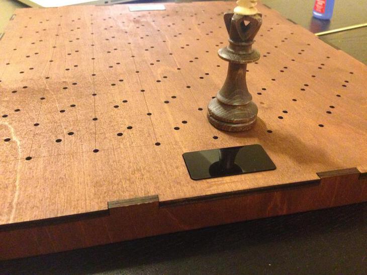
Alternatively, as a good engineer should always be doing, look for ways to take something that already exists and build upon the design. Some of the first files I ever sent my industrial designer was the theory of operation but also images of a chess board that looked similar to what I wanted to use.
Theory of Operation
Speaking of theory of operation. Much like a product requirements document, I set out to write as much information that I had in my head about how the product would work and put it into a well organized document. I ended up using a Markdown and Pandoc based document generator to keep track. Here were some especially important lines from my documentation that related to how the LEDs would work on the board. It was important for Brett, my industrial designer, to see this information so he could better help me visualize how the LED function of Cognos would work.
Section 4 - LED Indication
Similarly, in order to play a game of chess remotely the player must understand where to put his/her opponents pieces. Using a dot matrix led driver, LEDs that either surround or are in the middle of the chessboard spaces will light up to indicate where to place a piece, where a piece can be placed, or even provide helpful hints if playing a handicapped game or in an instructional mode. These LEDs are completely controlled by software and can be configured in many ways to adapt for different types of play.
When You’re Not On Your Own
At a company, large or small, this is the exact same process a professional industrial designer would go about creating concepts for a particular product. for instance, one of my buddies Greg (mentioned in an earlier post ), sometimes spends weeks coming up with extremely detailed drawings of the full product or different features that could be incorporated into the product before ever touching CAD.
If you ever get the chance to watch an industrial designer work, take the time and let them explain what they’re thinking. If you’re an engineer it’s a chance to understand a completely different perspective around the same product you’re making together!
In terms of Cognos, I ended up receiving back some great sketches that Brett drew up showing different aspects of the design that I had talked about in my theory of operation document. One of the first things that I asked him to do though was to create sketches before anything else. (Just as I had seen Greg do many times) That way I could pick and choose which ideas to refine before going forward. Here were some of his ideas around the product that never quite got to see the light of day.


Once we had a few ideas in our heads and they were down on paper, it was time to take those ideas and bring them into CAD.
Convert it to CAD
As I mentioned before, converting the concept drawings to CAD is the next step in the process. There are a few reasons you want to do this before moving forward:
-
First, you want to make sure that the form and function digitally makes sense. What do I mean by this? Measure everything on the screen and make sure that it is usable for the end user to interact with. We’ll go into the next steps of creating a physical prototype to further hone size and shape. But, if you can, optimize as much you can here.
-
Next, it gives you an idea of what your printed circuit board must look like. Circuit boards follow the size and shape of a product and not usually the other way around unless you have a pushy electrical engineer. In this case, I was wearing many of the hats but I was mostly concerned about product cost and ease of assembly.
-
Converting to a basic CAD sketch will help your industrial designer assist you with determining the final form and function of the design. Sometimes industrial designers can even test the functionality digitally before creating prototypes saving some very important cash in the process. Remember: they know little to nothing about how you’re imagining your product. You need to give them a hand as much as possible to realize your product.
It was relatively simple for Brett to get some of the sketches I had chosen into CAD. The most important part was to refine and choose the direction that we were going in before going to far. In this case, we were trying to determine the form and function of the buttons, but also the look and feel. For instance, what did it look like to have a finished wood top with a plastic or metal bottom? This was the time to experiment!
I do want to make an important note here that I did have a very good idea of how I wanted the product to look but I gave Brett the freedom to either converge on my already existing thoughts or go somewhere else with it. I wanted to see if he was going to go the same direction as I was imagining in my head. That way if he had a better idea about form and function - as he is the expert after all - I would be willing to listen and not shoot it down first thing.
Here was another early mockup which Brett ended up sending me.

This process, by no means, is the creation of the final design. This is an early step in the product development process.
What do you mean Jared? Can’t I just go to a factory and have them build it once it’s done?
My answer: Nope.
This process is for flushing out form and function not determining how everything goes together. You know that information when a mechanical engineer gets their hands on the model and starts breaking it down into every tiny little piece including screws! Don’t get me wrong here, an industrial designer needs to know the assembly process to ensure that they’re building feasible products. Without that core knowledge, a product could never see the light of day as it wouldn’t be manufacturable.
Iterating and Fine Tuning

Once you have a basic idea and a good CAD model of how you want things to look, it’s time to dive deeper into the final form and function of the product. As you can tell, there were several iterations of the design before coming up with something ‘final’ that could be officially prototyped or posted on a website for marketing purposes.
For instance, one of my concerns was how the lights would look on the board and what were the best ways to have them interact with the end user (if at all). Brett ended up making five light layouts (including the one above) to test which one may work best in a chess playing scenario. Again, I let him come up with as many ideas as he wanted though I may have already had an idea of what I wanted. We ended up going with layout similar to number three below.

 Again, this was all done before ever touching anything physical. I was trying to leverage Brett’s experience as a designer to ensure not only did things look good but they were fully functional as well. When designing a product, a large goal of yours should be keeping it functional and secondarily beautiful. Sometimes, when you’re lucky you can get both. 🍀
Managing the Back and Forth
A quick segway about managing the back and forth.
I do want to point out that creating these files and providing the feedback would have been absolutely crazy over email. I highly recommend creating a Trello page and managing your project there. That way you can stay up to date as to what is going on, ask for status updates and even send/receive files. As a backup, I always had my team send me files via Dropbox as well.
For instance, I created several different Trello ‘cards’ which indicated the different tasks of physically drawing concepts, creating some basic CAD mockups and also creating the top down LED views as you’ve seen in this section. I created several buckets which have been proven useful including:
- Pending tasks: these are tasks that me or my team members came up with that should be done in the future
- Assigned: these are the tasks that are assigned an can be worked on. Depending on how much freedom you may give your team, if they’re board they can take items out of Pending Tasks and start working on them.
- In progress: are the tasks that are currently in progress
- Complete & Unreviewed: once the work is complete but has not been reviewed the tasks go here. For instance, I would set up my Slack to message me when things were placed into this bucket so I knew that I could schedule some time with my team to review.
- Complete & Reviewed: once the work is complete and there are no issues after review it goes here.
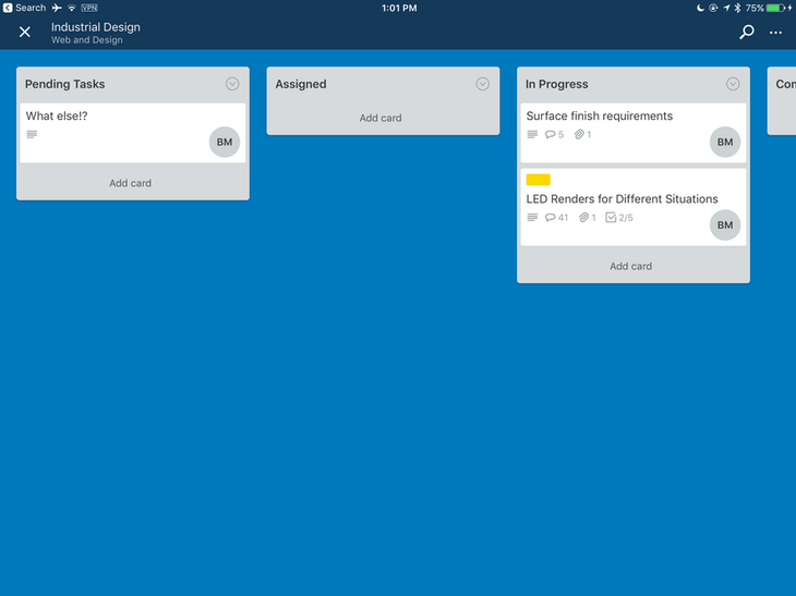
We were able to operate very well over this method and it was a pleasure to keep track of tasks and the project as a whole all from the same drag-and-drop interface.
Creating that (Mechanically) Functional Electronic Prototype
At some point during this process, it’s time to make a prototype. Not only to move the project forward but also to test lots of the assumptions that are made when designing the 3D CAD. Things like refining the finish, look and feel were secondary to actually testing the design. The only reason to create a more polished model is if you’re trying to market or sell your product (even if it doesn’t exist). There is a fine line between misleading potential customers and getting feedback. I err on the side of getting people to say Yes! I will buy your amazing widgets! so I know i’m on the right track. Otherwise, creating products will simply never be a money making venture.
So, once a 3D model is chosen as the baseline for some real life testing, it’s time to get our hands dirty. It depends on your comfort level and how much you can leverage your teammates to create the prototype that will best test your assumptions and to help guide future design and engineering decisions.
For instance, create a real life in-person non-functional form factor mock-up. The difference between a mock-up and a full functional prototype is that one does something and the other just looks pretty. A good friend of mine discussed his industrial design expertise on creating mockups in a previous article . If you need an idea of what type of material to use or how to get from one stage to the other I highly recommend checking it out.
For me, I decided to avoid the route of creating something in clay or foam and going right for the gold. I was going to make an (almost) fully functional form factor prototype.
There were many ways of doing this of course. I could have 3D printed the assembly and all the parts. I could have cast parts in clay or silicone. It was all too time consuming and out of my reach price wise. So what does one do when they have to create a rather large prototype? Create the parts by laser cutting it.
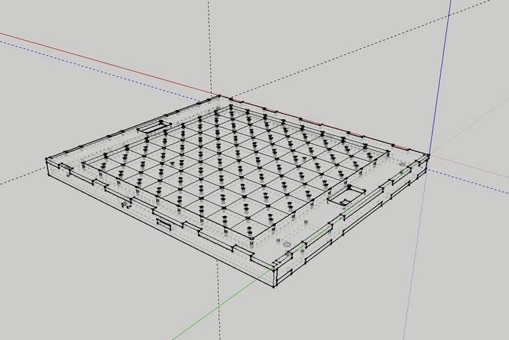
I ended up spending lots of time in Sketchup creating a model that I could subsequently break down into flat parts that then could be pieced together in my apartment with nothing more than a little superglue, paint and wood stain. The trickiest part here is that there is no easy way to get parts done in 3D. Let me explain:
For laser cutting, you take a uniform piece of flat plastic or wood and place it in the machine. It cuts out the shapes of your prototype as necessary. Then you pull it out of the machine and pop out the pieces much like you would puzzle pieces from a completed puzzle. In order to create something three dimensional, sometimes you have to stack a few pieces on top of each other to get the thickness or the features you desire. An example from Cognos, I designed some buttons that would go on the top surface of the board. The only problem is that it required not one but 3 separate pieces of plastic that needed to be glued together to create that one piece. It required me to think how I could create 3D parts using 2D methods.
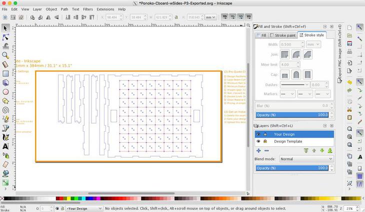
Here is a picture of one of the files that I ended up sending to Ponoko. As you can see there are duplicates for some of the smaller pieces because those would soon stack upon each other inside the prototype.
Laser cut parts can also be used in different ways besides attaching them directly to the product. At one point, I ended up creating a spray paint template that was used so create the checker pattern on my prototype that was so exact and perfect it brought tears to my eyes. 😭 (tears of joy of course)
Doing it Another Way
Of course, prototyping does not require you use the same technology for all the pieces. Sometimes you can get away with it sometimes you cant. Here are some of my favorite resources when it comes to prototyping and testing your product.
Fictiv - these guys do just about everything. They have a huge amount of resource on the learning portion of their website. Highly reccomend.
Molder - these guys have been around for a long while. We first used them to print 3d prototypes of the product we released the next year. They’re still around today which goes to show how valueable their service is.
Another favorite thing of mine to do is to leverage things that already exist. If you are not already familiar with McMaster Carr, you should be. McMaster has a huge selection and catalogue of all types of raw materials, screws, and mechanical widgets that could be used to develop a prototype. For instance, with Cognos, I ended up purchasing not only hardware to keep things together (screws and nuts) but also some small alignment rods, and springs for the board’s buttons.
And That’s Just the Tip of the Iceberg!
Once you have pieced together the parts, it’s time to test your assumptions about how things would work in the real world with real people. That means test exercise the functionality you think is important for the end user and then have someone who hasn’t been involved in the process also test it out. Having someone else play with your prototype, especially if they’re the intended customer, will pay dividends in the end.
If your stuck on the complexity or just how much work this may take, my biggest recommendation is to start somewhere. Find the smallest piece or portion of your project that you can prototype and test. When I say small, I really do mean it. Find something that is so small and seems trivial and get it done. Then you can move on to bigger and scarier things.
Looking to learn more about the product development process? Check out my top resources on product development and gain more insights to help you get past the slog.
Last Modified: 2020.3.7