If your product isn’t lasting as long as you want to, it may be time to do a current profile on your product and see where you can optimize power. This is a must for battery powered products and will save you from the dreaded customer induced headache 🤯 in the future.
Once you know how you’re going to power your product, it’s time to figure out how much power you can save with this handy technique.
The Tools
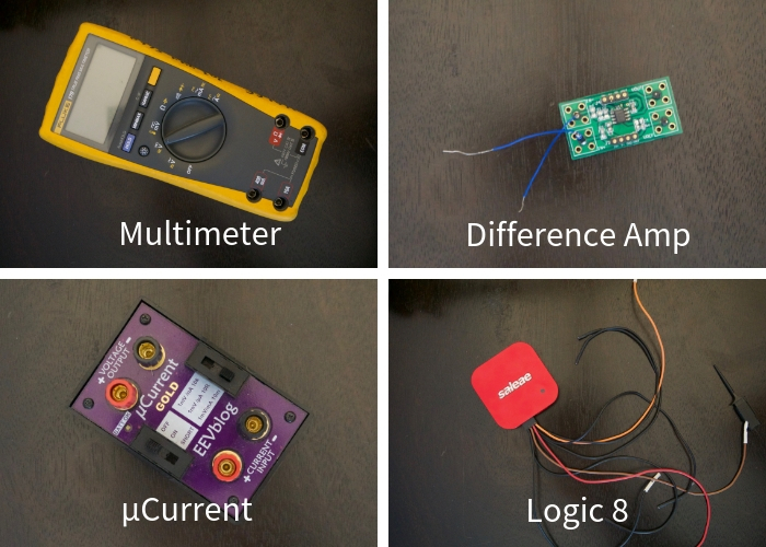
I use a Fluke 179, µCurrent Gold, a difference amplifier breakout and a Saleae Logic 8 for my current measurements. You can definitely get crazy with current measuring setups like forking over the money for a desktop multimeter. Why buy a Cadillac when all you need is a Camry? Plus, sometimes the cheaper tools prove to be way more versatile than the alternative.
Sidenote I have used desktop multimeters for current measurements and they’re not a bad idea. In particular, I’ve used the Keysight 34461A in the past with some decent results. The only drawback is that without writing some code and integrating somehow with the device’s GPIB (or emulated GPIB over USB if you’re lucky), it would be hard to graph the data. You will soon see that the Logic 8 makes it dead simple to log your current plots.
Hooking Things Up
There is a couple ways to hook things up. The traditional way is to hook the µCurrent directly to the multimeter. Like in the picture below.
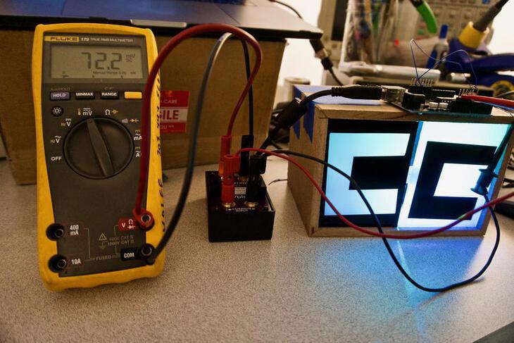
- Current Input + goes to your source.
- Current Input - goes to your device.
- Voltage Output + goes to the V+ on your multimeter (in mV mode)
- Voltage Output - goes to the COM on your multimeter
This is great for sanity checking or seeing what the static draw in a steady state is. For example, I’ve used this setup to see how much a device is pulling in sleep mode or in an off state. I will often use the averaging mode on my multimeter to account for small fluctuations. After all, we’re interested in what the system is doing most of the time.
Bluetooth devices are dynamic and knowing that fact we can’t just look at a multimeter screen and hope we catch all the highs and lows especially when in an active state. I’ll go one step further to say that it won’t “see” all the higher speed transients that may change your mind about how your circuit is designed in the first place.
One way to view a current profile over time is to connect it to a oscilloscope or an analog capture device like the Saleae Logic 8. I prefer a Saleae Logic 8 because it’ A) cheap and B) makes it easy to export the captured data and graphs for later use.
The drawback?
You’ll need a single ended signal to get the proper output. The reason being, the µCurrent is designed to monitor both positive and negative current. So the Voltage Output - pin is actually about half the working device voltage rather than 0V.
I whipped up one solution using a TI breakout board and configured a standard rail-to-rail op-amp in differential mode. Here’s the circuit diagram of how it’s configured.
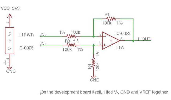
Sidenote: This is a unity gain configuration, so no amplification only subtraction between the two input pins. If you’re looking for precision, definitely use feedback resistors <= 1% tolerance. This particular board is stuffed onto the difference amp configuration of the DIYAMP-SOIC-EVM with a TI OPA196ID. Finally, as you can see above, I tied V-, GND and VREF together to unify the grounds on this little board.
Alternatively, more and more development kits come with current characterization tools. These only can measure positive current but in most cases that is sufficient enough for measuring current.
Powering it up
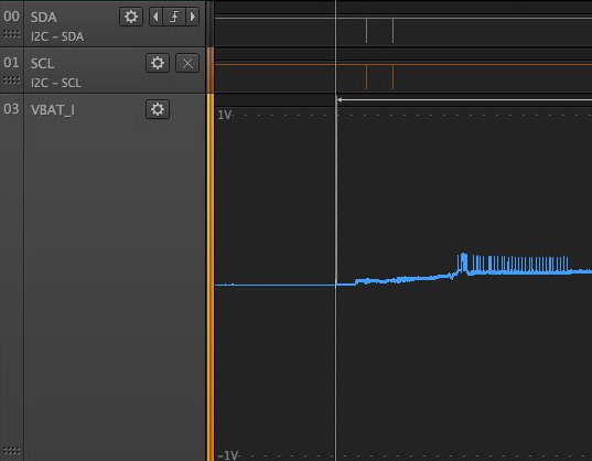
I recommend to power the device under test on a bench power supply. That gives you more control especially if you’re measuring “battery current.” If you do use a battery expect odd behavior and large swings in voltage when it gets closer to being discharged. See below for a capture of the battery voltage taking a dip during the beginning a transmission phase.
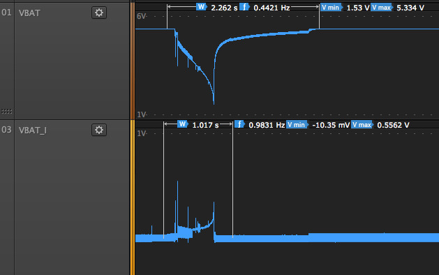
The combination of a discharged battery and the transient current caused the processor being powered to brown out and reset. So, best to start testing with a stable known voltage and then move on to testing with batteries.
Getting the device in the state you want
First and foremost measure the state that the device is going to be in most of the time. For most devices, that will be a sleep state or a low power standby mode.
So, get the device into that state, whether through a firmware update or waiting for it to turn off, and keep it there. Then, you can connect your multimeter and µCurrent together in the traditional configuration to make a measurement.
Easy peasy.
Then, you can proceed to measure other states to get a more wholistic view of the performance of your device. Here is an example list that may apply to a Bluetooth or IoT device:
- Off
- Deep Sleep
- Sensor Measurement
- Transmission
The last two states are a bit more dynamic and would require viewing the current plot over the time that each state is active. In a typical firmware design, I would want to batch these types of events together and get them done as fast as possible. In general, batching makes measuring these events much easier and will likely boost your products’s efficiency.
In order to use the Logic 8, you will have to make a slight modification to the “traditional” µCurrent setup. See the diagram below for a high level hook up guide.
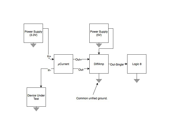
Once you have it hooked up, the best way to test is to put your device into a transmit mode of some kind and run a collection in Saleae Logic. The output signal of the DiffAmp should be responding accordingly. If not, make sure your DiffAmp is powered and the µCurrent is powered on. Run these higher captures in the mA mode on the µCurrent otherwise you run the risk of weird behavior, including saturating hte onboard op-amp, with a larger series shunt suppling your product.
Measuring
The Logic 8 can be used in two ways. You can trigger a capture on a rising edge (similar to an oscilloscope) or you can start the capture manually.
In either case, you’re trying to accomplish the same thing: get a current plot from the beginning to the end of whatever operation you’re doing.
For instance, the capture below is the beginning of a Wifi update to the cloud on a Particle Photon.
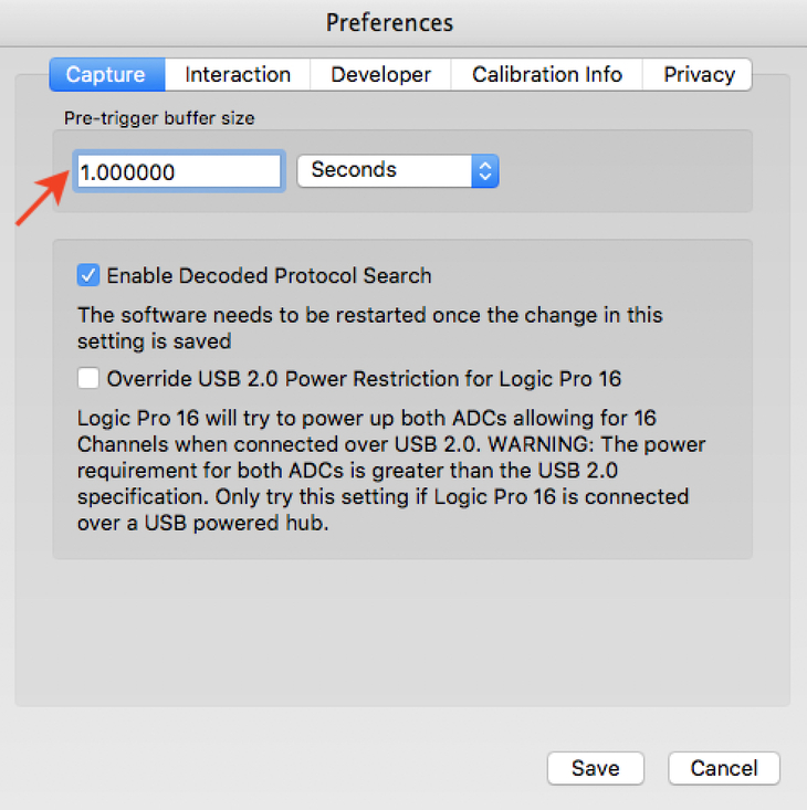
I set the capture duration to 14 seconds hoping that I will catch the full transaction. I outline what exactly the firmware was doing in the post I did on the circuit last week. Conveniently, you can also set the pre-duration in the preferences if you’d like to see the signal before the trigger.
Once you have a capture on the screen, you can add measurements and get peak readings. Unfortunately, Saleae doesn’t have a great averaging function but I hope they implement it soon. Averaging is what’s most useful because the average current of the device over time will dictate how long it will last on a certain charge.
Here’s an example of the measurement results from the Photon capture above.
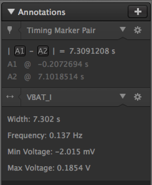
The most important things to look for is the time span that the device was on for, the average current and also the peak current. The peak current in this case was 184.4mA and the time was 7.3s. If I were to plot an average line it would sit around the 90mA level.
Conclusion
Now that you have some captures and some data to work with your can make both design optimizations but also, when optimized, you can use those numbers to calculate theoretical battery life. These theoretical battery life calculations are gold especially for managers and engineers to ensure that the device will meet expectations. Some devices are required to run for years so it’s difficult to test the full lifecycle but with these techniques you can get to the certainty you need to ship your product.
This is really only the tip of the iceberg when it comes to power management for battery powered Bluetooth and IoT devices. Stay tuned for more posts on the topic and if you signup for my free newsletter below you’ll be one of the first people to know about it.
Last Modified: 2020.3.7