
Self assembling circuit boards is the cheapest way to get components on circuit boards.
Period.
Don’t believe me? Believe these screenshots:
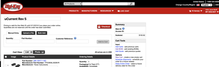
Self assembled: $143.84 + Tax & Shipping
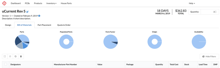
Professionally assembled: $362.83 + Tax & Shipping
That’s about $50 per board versus $120 per board. That’s huge. Plus 18 days is a long time to wait for three circuit boards.
In this post, I’m going to to talk about the biggest tips and tricks I’ve learned over the years on how to assemble my own circuit boards. I have no doubt they’ll be immediately useful for your current and future projects.
So, to start with let’s talk about CAD.
Export Your CAD
The golden standard for the industry is the Gerber file. Gerber files are the translation of all the pretty shapes, traces, pads, silkscreen and drills into something useful for a board fabricator. There are other formats out there like ODB++. If you’ve ever looked inside an ODB++ file though, it’s just a bunch of Gerbers packaged up. 🤷♂️
If you’re interested in learning more about Gerbers and my process of checking them, go watch this video and then come back. No worries, I’ll be right here.
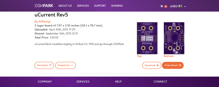
Fortunately, most vendors will take the raw CAD files especially if you use something like Eagle CAD. For instance, when I go to purchase a circuit board on OSH Park, I’ll upload my .brd file. In most cases, it gets promptly processed, and spits a price back.
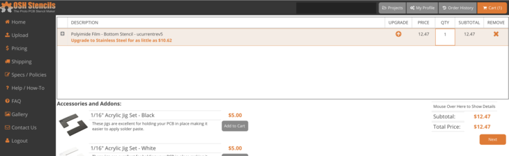
These same files can also be used for the purchase of a solder paste stencil. Solder paste stencils allow you to applicate solder paste only to the openings in the solder mask on your circuit board. Yes, you can assemble a circuitboard without using solder paste or a solder stencil but I highly recommend it especially if you care about the aesthetics of your board.
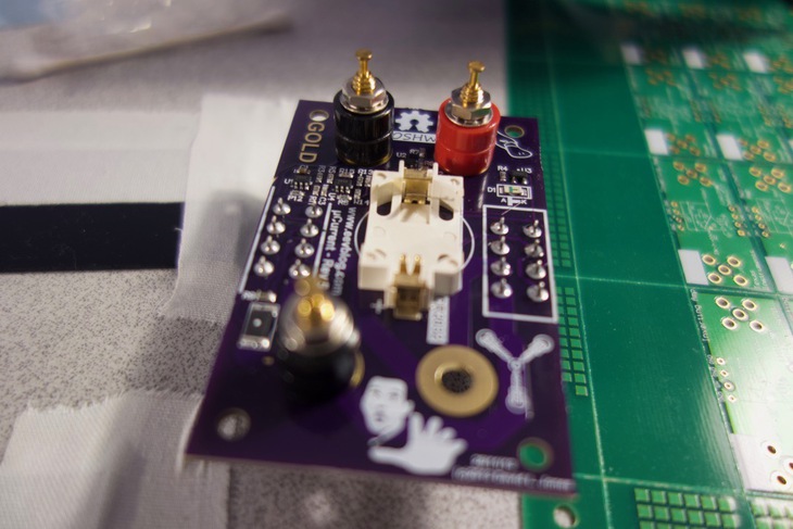
A side note about aesthetics: I recommend for early prototypes to include reference designators that can be visible when the board is fully assembled. It makes hand placement of parts 1000 times easier. See what I’m talking about below:
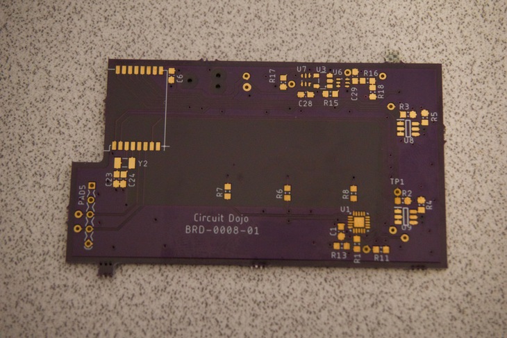
See all the reference designators in white? They’ll come in handy very soon..
For stencils, my go-to is OSH Stencils. Their cost is reasonable and saves a ton of time when assembly is underway. Plus, as you may have guessed, circuit board assembly lines use large metal stencils to accomplish the same thing.
Finally, you want to export your bill of materials. I use the bom.ulp script that comes with Eagle. I always export by value so all the parts of the same attributes get binned together. This results in a clean and compact BOM that can be easily imported into something like Octopart. I often use Octopart to research prices. If it’s a particularly large bill of materials, I may split orders between say Mouser and Digikey. Sometimes even Arrow has parts for dollars less than the other two.
When ordering, all vendors allow you to import a .xlsx file or .csv. When importing, sometimes you get choice of putting in a customer part number (or similar). You can use this to store the reference designator. That will get printed out onto the label that they stick to the bag.
As long as your parts are not too heavy you can typically use the First Class mail option that Digikey offers. It looks like they have recently raised their shipping prices (used to be $3.5 now it’s ~$4.5 to Connecticut) Parts usually arrive within 2-3 business days. Which is not to bad! 📬👍
Pro tip: Once you get the parts, double check your inventory. I’ve made the mistake of not ordering enough parts for multiple assemblies. If you do find yourself short, just make another order. If you don’t you could be unpleasantly surprised when build day comes and your short components.
Placing Parts On Your Board
Set up your assembly location. Use the plastic cutouts and place them around your circuit board. Then tape them down as a permanent frame to your desktop. You can make them yourself by using a service like Ponoko or just buy the ones that OSH Stencils offers.
Then, tape the stencil over the top aligning all the holes. This takes some time and finesse. Make sure you tape it down so it doesn’t move.
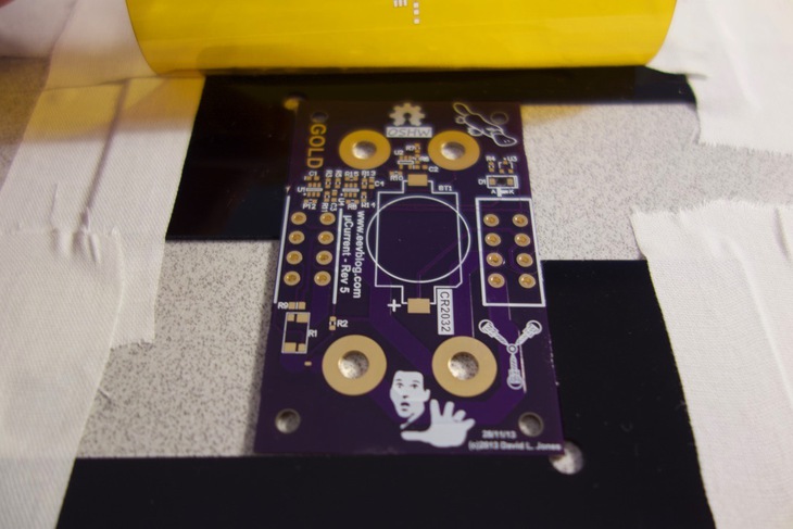
Place the stencil flat on the board. Then, take your solder syringe and glob some solder across the top of the stencil. Use an old credit card or the plastic card that comes with a stencil to spread the solder. Try to spread away from where the stencil is attached to your work surface. Otherwise if you move the stencil you’ll make a mess and have to start over.
Once the paste is down, like the picture above, place the board on a flat surface. There is nothing to hold the parts on the board so it’s best to place it on a larger unpopulated circuit board. That way you have a movable base and there is less risk of destroying your hard work. Plus it protects the surface underneath once you get to the next step.
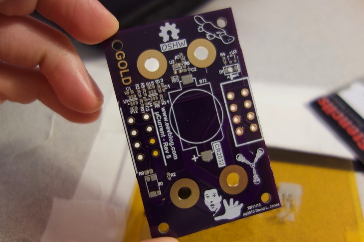
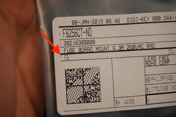
Remember, use the reference designators on the circuit board and compare with the reference designator on the packaging of your parts. As long as you exported your BOM correctly there’s no reason to go back and check part numbers. See an example of packaging with the reference designator below:
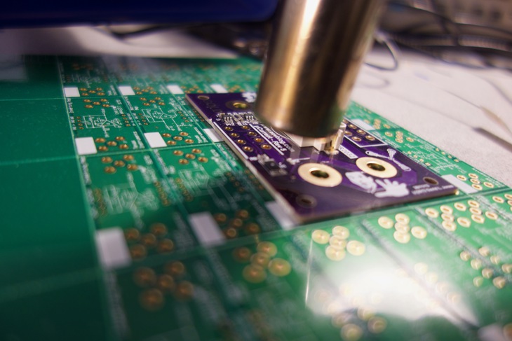
Finally, bake your circuit board. I typically using my hot air gun at about 380°C and slowly go around the whole board soldering all the parts. My airflow is set to very low when I do this otherwise the parts go flying. This applies to any hot air gun setup.
This also can be accomplished by using a hot plate or old toaster oven. Remember, you do not want to use the same oven that you use to toast your toast!
Extra precaution: some salty engineers out there think there’s nothing wrong with breathing in fumes from soldering. I’m very much so in the opposite camp. Not only are you handling heavy metals (less of an issue with lead free solder) one way or another but the fumes from the solder flux are noxious. Best way to fix this is to run a fan out the window or use a fume extractor.
Time to Play
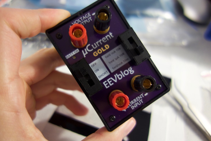
So you’ve ordered all your parts, stencils and boards. You’ve patiently and dutifully assembled and soldered all the components. Congrats, you’ve made it to the big times! Next stop is testing, firmware development or whatever else you need to do with your design.
Also, to be fair, I actually have nothing against companies like Macrofab. They provide a great service and I’ve actually used them before for other projects. Just remind yourself of the cost/time benefit of someone else doing the work for you. Is it worth it? Only you can decide.
Building your own circuit board on the cheep no only saves money but it’s rewarding when it’s all done. When building new devices and prototypes for my clients, I always keep this process as an option. It allows me to get a better idea of how a circuit may work before ever having to plunk down a ton of cash for a machine assembled board.
Curious to learn more? I talk about these topics and more on my mailing list. Click the button below to get yourself signed up.
Until next time,
Jared
Last Modified: 2020.3.7