Populating (or stuffing) circuit boards can be a messy process. Its fraught with high heat, chemicals and teeny tiny parts. What could go wrong? In this post you’re learn how I assembled the first prototypes of the nRF9160 Feather. It’s my first full on collaboration with Hackster and GroupGets. Which is quite exciting!
This post is lengthy but you’ll get all the nitty gritty details of the build. Ready?
Prepare for Greatness
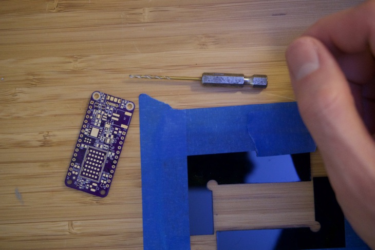
If you order boards from OSH Park, you’ll notice that your boards come with sharp barbs usually on every side. These are leftover from panelization and need to be removed. My tool of choice for this is to use a 1/8" 4-flute end mill and my Dremel. You can see in the picture below the “barbs” i’m talking about.
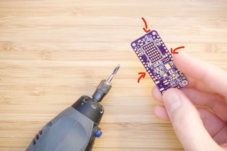
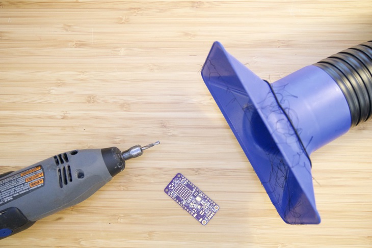
Though it does push some dust around, its by far the easiest methods beyond putting it in a CNC de-panelizing machine. And oh, if you’re doing this yourself, make sure you suck away the debris. You don’t want to breathe that stuff in!
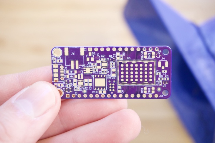
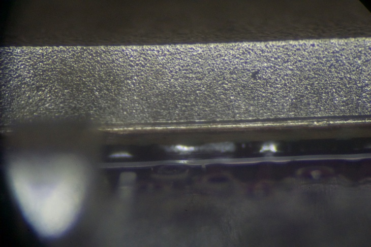
After some careful grinding it should look more like this:
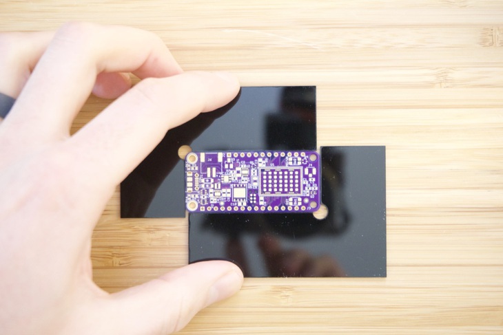
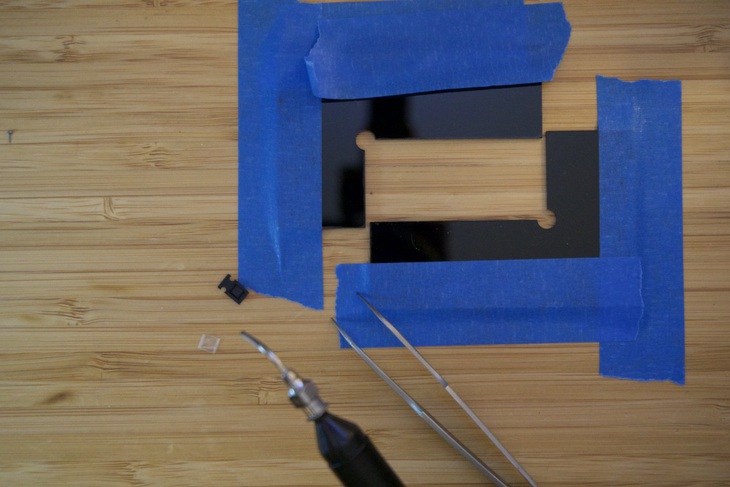
The main reason we do this at all is because of the next step: dispensing paste. This allows you to secure the board so it won’t move when you’re trying to carefully place paste in the right place. In my case, i’ve used acrylic pieces which are very similar to the ones that OSH Stencils sells.
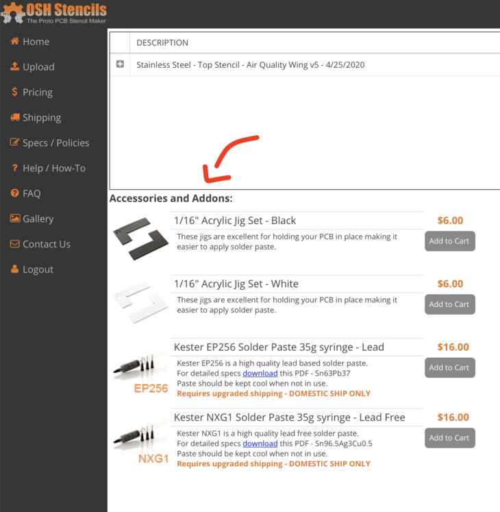
If you don’t have access to a laser cutter, this is your best bet!
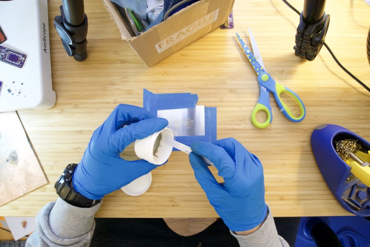
Next you’ll need some masking tape and the boards you’re working with. Lay them flat on the table and push the ends together.
Then use your handy dandy masking tape to hold the fixture down so it doesn’t move.
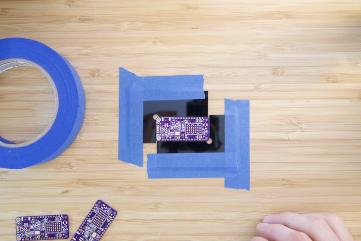
One thing that I noticed with the nRF9160 Feather board is that the Z-height is slightly smaller than a standard 2-layer from OSH Park. (This board is 4-layers) I simply removed the protective coating on the acrylic and it helped move the board just above the acrylic. 👍
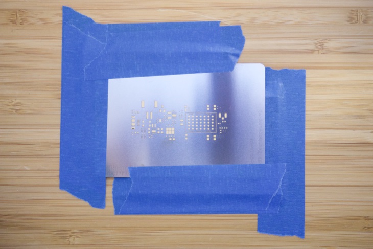
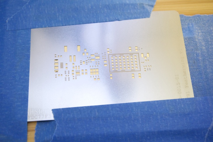
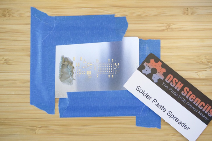
I then placed the stencil over the board. Aligning all of the solder mask openings can be tricky. I always use opposing corners to make sure i’m “square”. A good rule of thumb is if you see all gold color coming through the stencil holes, you’re good! I’ve screwed this part up many times so I recommend take your time here.
At this point you should be ready to dispense paste. I’ve cut one of OSH Stencil’s cards into a smaller spatula. That way I can retrieve solder from the paste jar. I’m currently using this paste for this board.
One thing that I did not realize about the paste when I bought it is the paste type. We’re not talking about lead free or leaded. We’re talking about how big the solder balls inside the paste are. The bigger they are, the larger openings you need in your stencil. A big thanks to Matt, one of my mailing list subscribers, for pointing out this important detail!
Fortunately, this solder paste is Type 4 which means it will certainly work for this prototype board!
I dabbed some of the paste on the stencil and used the other half of the OSH Park card to squeegee it across.
The squeegee process takes some practice. I’ve yet to master it. Thankfully there are machines that do this much better!
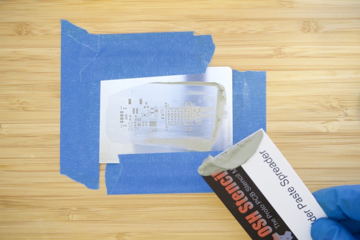
This is also the main reason why you want to secure your stencil well before applying paste. Otherwise your stencil will shift and you’ll have to wipe and redo. No one likes to wipe and redo!
Once complete, i’ll undo the tape on one side. Then, I’ll lift it over and get it out of the way. Slow and with control though!
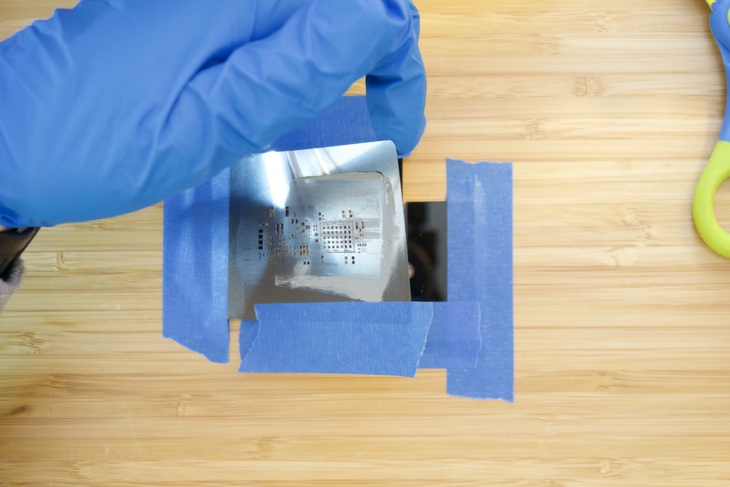
If you look closely the paste closest to the USB connecter got a bit.. messy. That wasn’t my concern though, my concern was the nRF9160 module. Those, at the time, appeared to look ok!
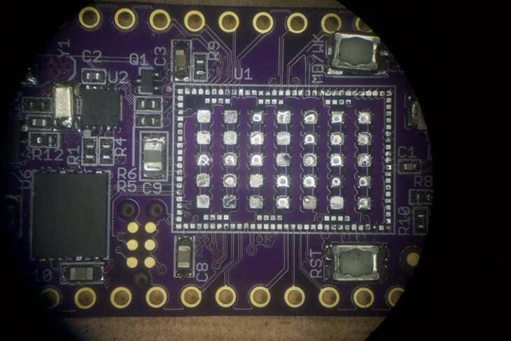
Here’s a close up using one eyepiece on my microscope.
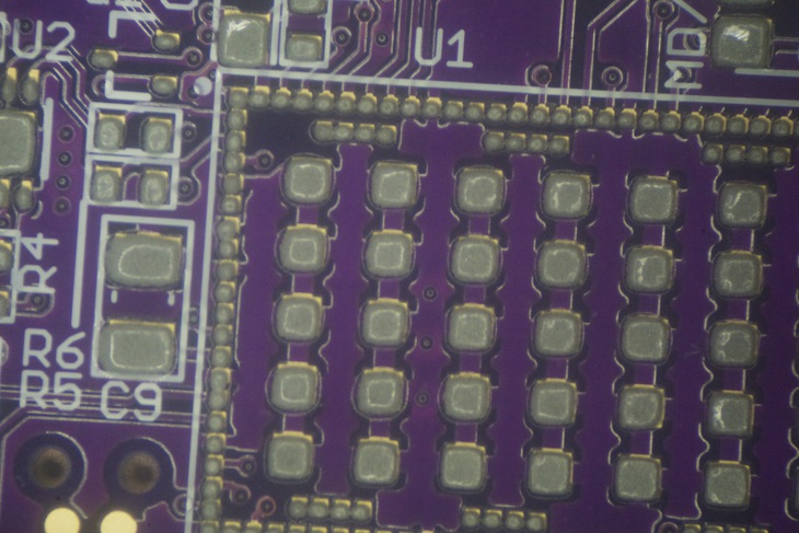
Not bad. A little off but otherwise worth a try. In retrospect I should have seen warning signs that this would not work but we’ll get into that later.
Assemble it
So we have solder paste on a board, now what?
Assemble all the bits!
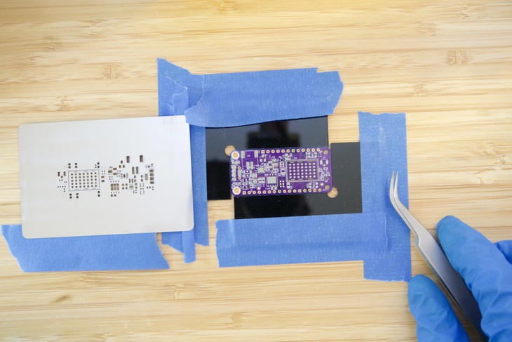
I’ll typically remove the board carefully from the acrylic jig. Then i’ll start placing components where they need to go. I’ve primarily used tweezers but i’m also experimenting with a suction mechanism.
While my hot air machine has this functionality, i’m in the process of building my own. (It doesn’t have the features like a nice foot switch. Plus it doesn’t shut off the hot air when pick-and-placing.)
One thing you should do if you do build your own boards: print out a black and white copy of your schematic. This will help you figure out what parts go where. Also, if you didn’t notice earlier, every part on the nRF9160 Feather has a reference designator somewhere near the component. That way you don’t have to keep referencing your board files during the assembly process.
Let It Flow
So, after carefully placing every single component it was time to flow some solder. Yup, it’s time to apply heat!
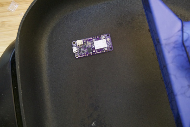
About a year ago I read about how other folks bake their boards. Sometimes they use toaster ovens. Some buy cheap Chinese ovens designed for the job. In my case, a used Oster skillet was all I wanted.
So for $15, I picked one up at the local Goodwill and i’ve never looked back since.
As you can see in the above picture, I position my boards over the coil and crank it up all the way. You also see that I use my fume extractor for filtering the air. Without that guy i’d probably have all types of cancer. So thanks Hakko.
Side note, here’s what the inside of my FA-430 looks like:
Where do all your solder fumes go? #notmylungs I've been using a @HakkoUSA FA-430 for years. I'm sure I've kept years of my life because of it! pic.twitter.com/8hOKatkx3A
— Jared Wolff (@jaredwolff) May 11, 2020
After checking that all of the solder had wetted I also checked the module. Simply taking a pair of tweezers and nudging the module is a good sanity check. That way you know if the solder underneath is hot enough. If it moves and then bounces back when you move the tweezers away, you’re done. If it, A) doesn’t move or B) moves but doesn’t go back your board needs more time in the heat. This especially applies to parts with pins underneath that you normally wouldn’t be able to see.
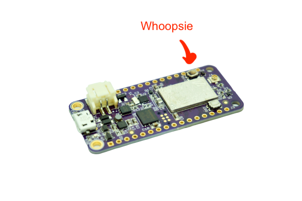
After removal it’s time for inspection! Unfortunately, I found a few issues:
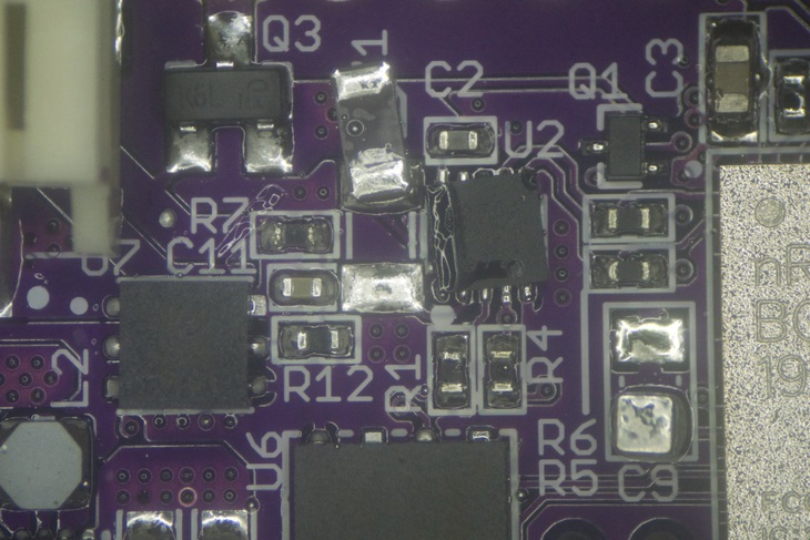
I’m not quite sure how this one happened but it was likely due to mishandling. You can also see that the giant 0805 cap had tombstoned. So much for being careful! Fortunately, these are easy fixes. The next problem though, is not an easy fix:
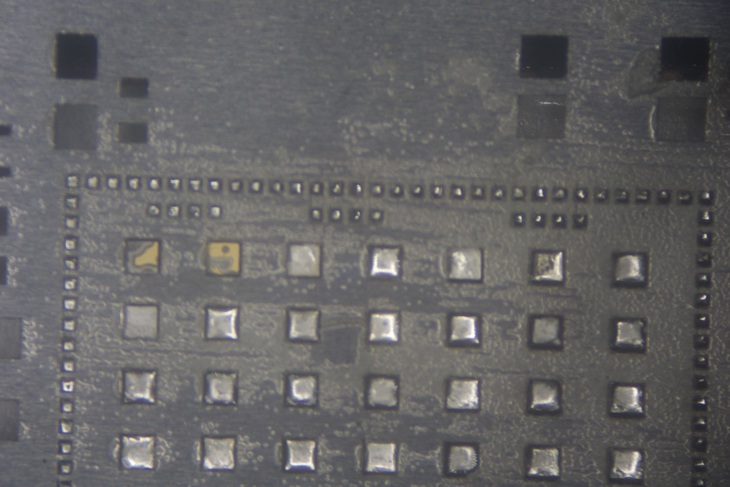
Those are the tiny 0.3mm x 0.3mm pads underneath toward the side of the nRF9160 module. What’s wrong? They’re shorted! Crap.
As I looked around at each edge of the module, I noticed a similar pattern. Most of the pins were shorted to each other.
Damnit.
The Debugging Begins
So, I held the board in place with a 3rd hand and removed the module. This requires two things:
- Patience
- Large tweezers
Using the hot air at about 370°C on a medium speed i’ll cook the underside of the board. (Heating the top will ruin parts like buttons, connectors etc) I did the same tweezer trick as earlier to know when the solder is hot enough. (Give it a very gentle tap and see if it moves and bounces back) If you find yourself in this situation, never force removal. Otherwise you’ll end up with ripped traces and pads!
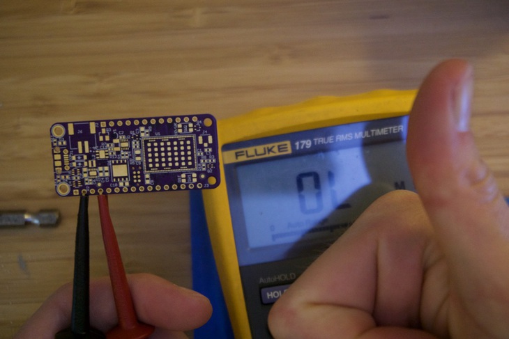
So instead of re-applying the module immediately, I decided to test the power supply and charger. Good thing I did because they weren’t working. Why? The 3.3V rail was shorted to ground.
At this point I started removing parts that I knew were connected. Off went the power supply. Off went the flash chip. Still shorted.
Crap
I went to check the unpopulated boards and low and behold: shorted. So, in a moment of desperation I reached out to Dan at OSH Park. He got back to me relatively quickly with the answer: slots.
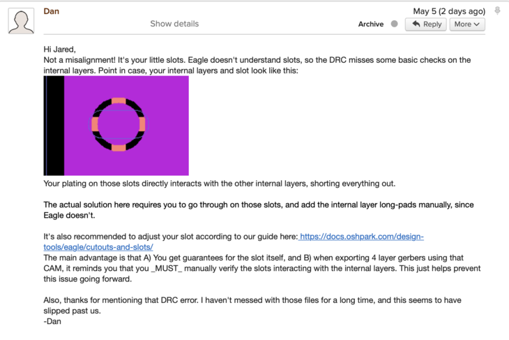
It turns out that I totally neglected the fact that my 4 layer board was using a footprint with slots! The part in question was the USB connector. Because the slots are plated it created a short between the middle two layers. (OSH Park’s documentation on slots is great. Make sure you take a look if you’re using slot!)
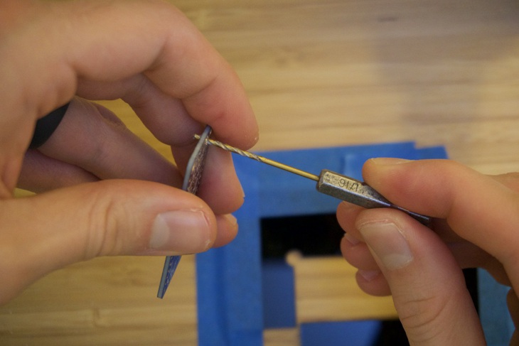
There was a way to salvage the situation though: drill out those holes! Fortunately there are no other traces or signal near the offending slot holes. So, simply finding a bit thats a little bigger than the largest diameter of the slot should do the trick. In my case I used a 1/16" bit and cleared out the slots by hand.
Talk about a low tech solution to a “high tech” problem!
After a quick continuity check, I was back in business!
Reassembly and Current State
Now that the board isn’t shorted, I made quick work of replacing the regulator and the flash chip. I typically take a tooth pick and apply a small amount of flux. I warm up the board a bit which allows the paste to turn into a liquid and evenly coat the solder surface in question. I recommend a flux like this one here.
Now, for the module.
I was recently inspired by a bunch of folks posting their iPhone chip transplant videos. (Here’s another) (I originally saw it on Instagram but I have no clue how to find it now) So why not use the same technique on the module itself.
So I placed the top side of the module on a 3M strip. Then I placed the stencil on top lining up the openings with the pads on the module. Eventually I got it to look like this through the microscope:
I applied pasted, removed the stencil and used my hot air to apply heat. In the end I had a modules with pre-soldered balls. Then, laid some flux on the board and prepped it for heat. I placed the module using the silkscreen outline as a guide and heated it up. Once hot enough I made sure that the whole chip was hot (using, again, the tweezer technique).
Once I was good there, I got under the microscope and checked the pins on the outside of the module. They looked much better. Still, there were some pins that didn’t get enough solder so they were floating/open. After some tinkering I got most of the pads I needed to proceed. (It definitely was not an ideal process, i’ll likely revisit this again when I screw up another module. 😬)
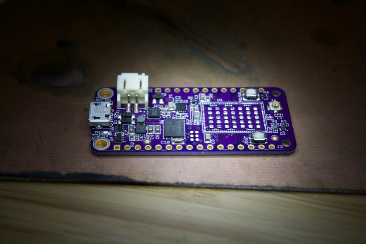
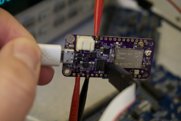
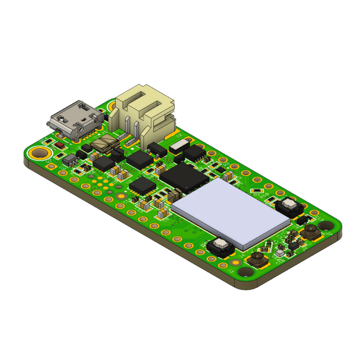
Here’s the board fully assembled. You can see that one of the buttons got a little.. toasty. (Still works though!)
Despite that, I was able to talk to the device using a nRF52 development board. Unfortunately though the J-Link on any nRF52 development board will not work with the M33 processor inside the nRF91. The nice thing is that the nRF53 board has a similar M33 processor. So with some luck I should be able to develop using that Development Kit rather than the $150 nRF91 one!
Coming Fixes and Improvments
There are definitely some fixes and areas of improvement on this board.
The first glaring issue is the footprint of the nRF91. I originally sourced the footprint from SnapEDA. They’re a great resource but you have to be extra diligent to make sure the footprint matches your part. Assuming the parts just work is a baaaad assumption. Here’s a side by side of what it looked like before and what it looks like now:
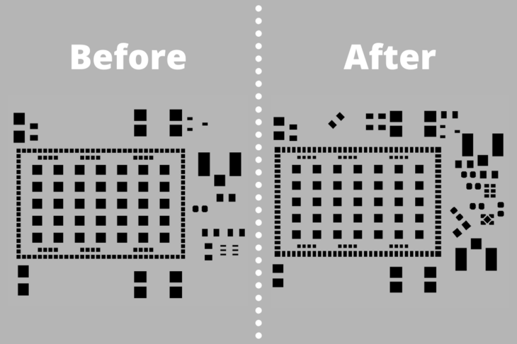
You can see that the outer pads got skinnier and longer. Both the pads and the paste openings are the same. Much of this was based on Nordic’s Thingy91 reference board and Nordic’s Devzone.
Other improvements that didn’t make Proto1
-
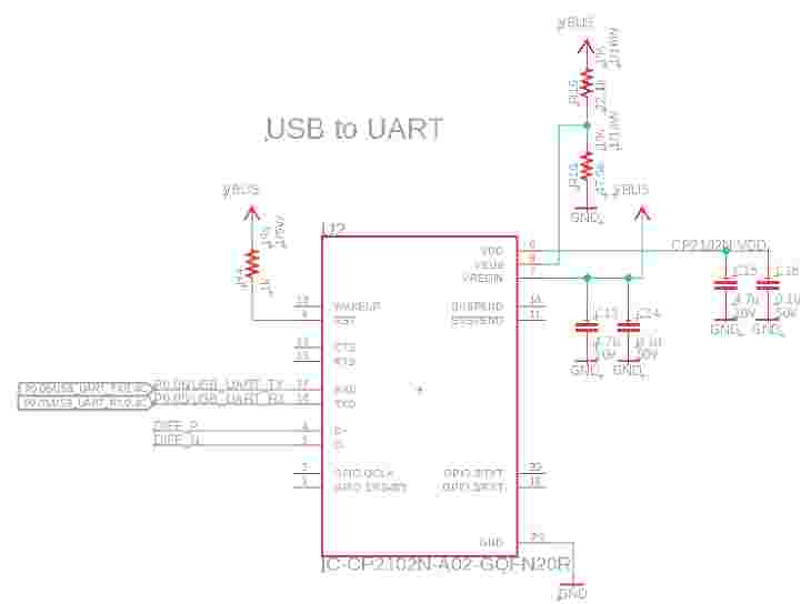
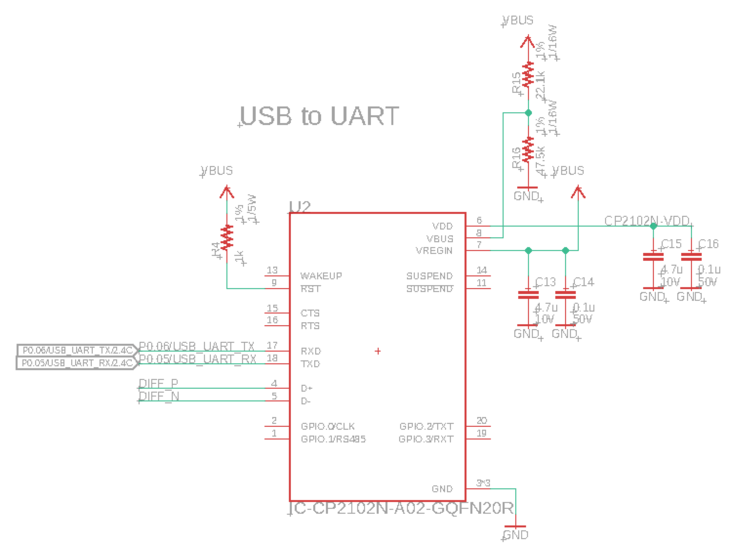
I did not include a USB-to-Serial IC. I’m most used to using a Tag Connect for all my development but then I realized that most folks may not have them!
-
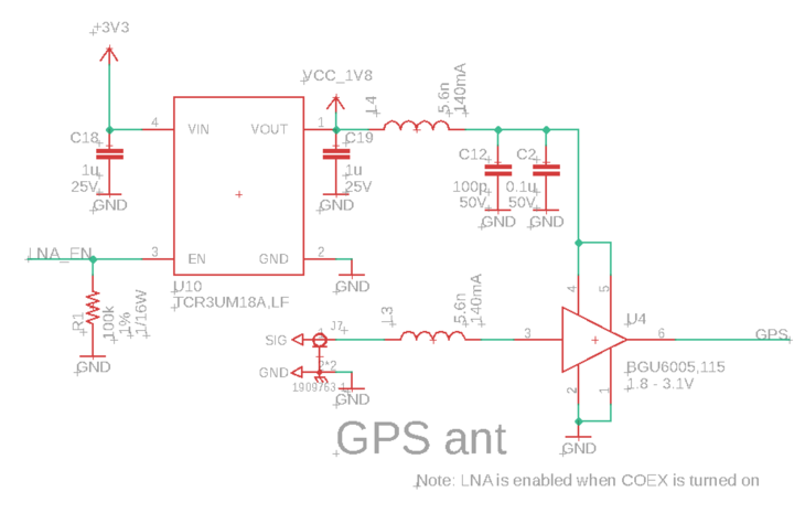
I also did not include the necessary circuitry for GPS. Proto2 will have al the necessary circuitry to make GPS happen. Here’s a schematic snippit:
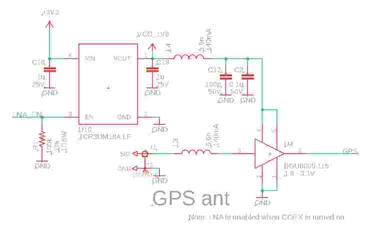
It’s using an 1.8V LDO + LNA combination. The LNA is a BGU6065 which is specifically tuned for amplifying GPS signals.
With those features added, the top side of the board is packed to the gills. I still could likely add some other components but not after some serious finagling!
More coming soon!

This is but the tip of the iceberg. I’m excited to share more about the nRF9160 Feather as I continue to make process. If you haven’t already check out Hackster Launch and GroupGets. Without them there’d be no nRF9160 Feather!
Also, if you haven’t already subscribed to updates, you can join the list here.
Until next time!
Last Modified: 2020.10.9