I was stressed out.
The startup I was working for just closed its doors. Having a family to take care of, I was on edge. I had a tightness in my chest that didn’t quite go away. The onset of panic came in waves.
To take my mind off things, my wife and I decided to get out of the house. One of my best friends was back in town. We met up and talked about life and the people we knew. We sipped on some beers in the mostly empty restaurant. It was a period of well needed respite.
Soon though, the conversation came to work.
::cringe::
Gregg went on to describe the lack of resources that was needed to get their latest hardware creation done. He was frustrated to say the least.
I was intrigued and started thinking out loud about how I could help his company and make it a reality. Both of our significant others were there so we didn’t get far.
Shortly after he arrived back in San Francisco, we continued the conversation. It became apparent that this was going to be a mutually beneficial business relationship.
I was hired and was handed the keys to the project.
A lot happened between then and their recent announcement of their new foot traffic sensor. At the very least, a few hundred hours of work, testing, communication and even a factory visit!
So, today I’ll share the steps that I took from “taking the keys” all the way to getting their foot traffic sensor to production.
Step 1: Understand The Requirements.
Understanding the requirements of the project is critical. Would you ever get in a car to go someplace and then drive around with no sense of direction hoping to get there?
I think not!
Requirements can take on many forms. They could be documented in a well detailed product requirements document. They could be a core feature set defined in an email. They could be a series of Asana tasks. (What ever tickles your fancy!)
Despite being thorough, usually requirements documentation requires work. I often find myself asking questions like:
How do you want X to work when Y happens?
How long do you want your device to work during ABC?
This may become a back and forth but it’s the difference between a working product and a paperweight.
Step 2: Prototyping.
Next, absorb the requirements from step one and start making something from them.
For instance, Dôr had some interesting requirements on the types of batteries they could use. This required a set of power supplies designed to accommodate not one but two sets of completely different battery chemistries.
Prototyping involved manufacturer dev boards, some soldering and lots of wire wrap. Once I had these circuits assembled, the next step began..
Step 3: Testing.
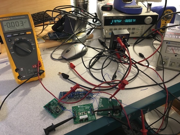
Testing can mean different things at different times. Sometimes it’s the validation of a circuit. Sometimes it’s checking the edge cases. Sometimes it’s using the product over and over until you’re convinced it’s going to work.
You should never go directly from a schematic to a circuit board unless:
- You have experience with that circuitry in the past
- You’ve prototyped and tested that circuitry as described above.
Creating circuit boards without testing (or experience) is a big waste of time. So mitigate that risk!
Step 4: Schematics.

Once you’re confident with your testing, it’s time to get one step closer to making it all a reality.
This is the process of creating the connections of a circuit board. There’s lots of details that go into the schematics. Consider them blueprints of your electronic product.
The most important part for me is building as much information into the schematic as possible. That way you spend less time outside the schematic and more time finishing your design!
I now use a ginormous library with hundreds of parts with part numbers, values and tolerances filled in. That way I can recycle designs and help get clients work out the door with little to no mistakes.
Step 5: Circuit Boards.
While a schematic defines how everything is connected together, the layout is how it will look in real life.
This is a detailed process and is quite prone to error. One pin, one connection, one incorrect pad size can throw off a design. The more that can be reused from a library saves a great deal of pain and heartache later down the road. Thus another great advantage of having a proven and reusable library!

Another important aspect of the circuit board is how all the components will fit. Will the components be too tall? Will they collide with walls or features?
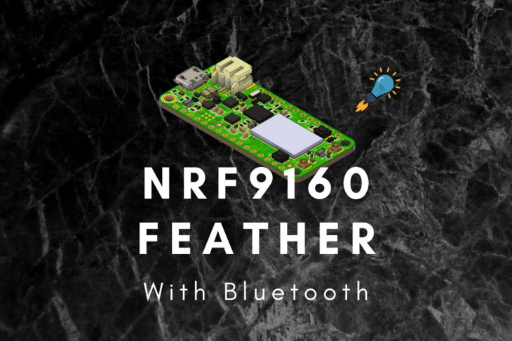
Different CAD packages have different solutions. For Eagle CAD, they allow you to attach STEP files to each component in the library. When everything is mushed together, it looks something like the screenshot above.
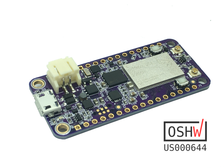
But don’t take my word for it. Compare the board above with the one I hand assembled myself:

Look familiar?
The best part is that the 3D files can exported. That way they can be imported into a mechanical model and checked for fit. All of that can be done before a 3D print or tooling is cut.
Step 6: Testing.
We’re back to testing.
While the heading is the same, it doesn’t mean that we’ll be doing the same things as earlier. At this point you’ll have populated circuit boards. This is a great point to start testing reliability. Besides that, some of the major things to look during this phase are:
- Confirm the circuitry is working the way you intended
- All programmable ICs can be programmed
- Communication signals are working
- Sensors reading the data as expected
- Power draw numbers are close to what’s expected
A checklist can be formed before the boards even get into your hands. I will often make checklists for my clients. Checklists help reduce errors immensely. They’re so handy that these days critical to the standard operating procedures of cockpits and operating rooms.
Once things are looking good, there’s one more step in the process:
User testing!
Exposing product to real users is the ultimate test of an electronic device. This will often answer these questions quickly: Will it survive? Was it engineered properly?
Only time and feedback can tell.
Step 7: Ramp
Barring any issues with testing in the previous step, the circuit board and electronic product is prepared for production. This is when the final bugs are worked out of the product and production line. That way the product can smoothly transition to higher volume processes.
A checklist for this step in this process looks something like this:
- Circuit boards are being assembled correctly
- Circuit boards are being tested properly using factory test software
- Circuit boards are installed into mechanical bits properly
- Labeling and accompanying documentation is placed on or with the device
- Everything is placed into packaging and prepped for shipping
This is a simplified list but covers some of the most important aspects of pre-production ramp.
As long as everything at each step looks good, you’re ready to go to production.
Step 8: Production
This is the step that everyone knows about. It’s where the rubber hits the road. It’s also the most stressful.
Lots of money goes into the production of physical tangible things.
Components that go onto circuit boards require weeks of preparation. Logistics is typically a nightmare. That’s why I typically focus on parts and components that common and in stock for my clients. That way they spend less time waiting and more time pumping out electronic devices for their customers!
Conclusion
The above steps may feel daunting but they are necessary to build electronic products. There are tips and tricks to getting through each stage faster but it requires experience and the right processes in place to make it happen.
I’m thrilled that I was able to help Dôr engineer the next version of their foot traffic tracking device. I’m excited to see them in customer’s hands (and on their doorframes)!
Curious to learn more about how I can help you deliver on your product goals? Subscribe to my free mailing list below. There’s plenty of tips, trick, hacks and more coming and I don’t want you to miss any of it!
Last Modified: 2020.3.7